C-30-108-000/VC-001 - Corrosion Control Procedures

1993-12-2094 Pages

C-30-108-000/VC-001
Corrosion Control Procedures
Iltis Canadian
Issued on Authority of the Chief of the Defence Staff
OPI: DVEM 3
1993-12-20

Part 1 — Introduction
Purpose
1.The purpose of this instruction is to describe the operations and resources required to implement corrosion control repairs to restore all vehicle bodies and safe serviceable condition and improved corrosion resistance.
When Repairs Shall be Embodied
2.The corrosion control repairs described in Part 3, Section 1 will be carried out only as necessary. The extent of the repairs required will be determined by following the inspection procedures of Annex A.
Installation Affected
3.Vehicle body.
Equipment Affected
4.All ECC 121501 Iltis Canadian. Corrosion control procedures for SEV installations are specifically excluded from this instruction.
By Whom Work Will be Performed
5.This instruction shall be carried out using second line maintenance services, or as otherwise directed by NDHQ.
Resources Required
6.The following resources are required:
- Manpower - The manpower required to complete the repairs on this vehicle are:
- Vehicle Tech 411
- Mat Tech 441
- Materiel - The items required are listed in Figure 1-1. Only those items necessary as indicated during the inspection (see Annex A) will be ordered.
- Special Tools Required - The special tools required and instructions are listed in Figure 3-4-1. Functionally equivalent tools are acceptable.
Weight, Balance and Stability
7.NA.
Reporting Procedures
8.Raise a CF 1020D work order. Enter ‘B’ starting in column 63 of the Supplementary Data block of CF 1020D. No special coding is required for the workorder number assigned.
Recording Procedures
9.Insert all costs associated with corrosion repairs, labour and parts on CF 1020D.
Figure 1-1 — Stores Required
| Item | NSN | DWG./Part No | NSCM | Description | Qty |
|---|---|---|---|---|---|
| 1 | 8010-21-576-5353 | 1GP-105M | 35068 | Primer, Red Oxide | A/R |
| 2 | 8010-21-880-9650 | D-84-010-001/SF-001 | Paint, IR Green (5L) | A/R | |
| 3 | 2590-21-911-1361 | 9377435-1 | 35807 | Holder, Flag | 2 |
| 4 | 6790 | 35342 | Sealer, Seam, Body, Silaprene | A/R | |
| 5 | See Figure 1-3 | 9377436 | 35907 | Patch, Panel, Side, Front, Left | 1 |
| 6 | See Figure 1-3 | 9377436 | 35907 | Patch, Panel, Side, Front, Right | 1 |
| 7 | See Figure 1-4 | 9377437 | 35907 | Patch, Panel, Side, Rear, Left | 1 |
| 8 | See Figure 1-4 | 9377437 | 35907 | Patch, Panel, Side, Rear, Right | 1 |
| 9 | 2510-21-911-1341 | 9377438 | 35907 | Strut, Rear Fender (*M) | 2 |
| 10 | 2590-21-899-5813 | 193860807A | D9134 | Support, Container | 1 |
| 11 | 5320-99-130-2425 | MD545BS | K0017 | Rivet | 2 |
| 12 | 2510-21-899-5818 | 183801515B | 98883 | Cross Support, Rear Floor Support transversal | 1 |
| 13 | 2510-21-899-5820 | 183801521 | 98883 | Plate, Rear Floor | 1 |
| 14 | 2510-21-899-5819 | 183801517 | 98883 | Support, Centre | 1 |
| 15 | Nissan | 24428-60L00 | S4504 | Drip Tray (*M) | 2 |
| 16 | 2510-12-173-8572 | 183846423 | D9134 | Frame, Windshield, Lower | 1 |
| 17 | 2510-21-911-1342 | 9377439 | 35907 | Cap, Crossmember (*M) | 1 |
| 18 | 5315-00-080-1936 | B-367 | 94223 | Pin, Clevis, 5/16 x 1-9/16 (*M) | 2 |
| 19 | 5310-00-167-0820 | 656-045 | 94223 | Washer, 5/16 STD (*M) | 2 |
| 20 | 5315-00-839-5822 | CP-17 | 94223 | Cotter Pin, 1/8 x 1 (*M) | 2 |
| 21 | 5340-21-911-1167 | 9377441-1 | 35907 | Leaf Butt, Hinge, no Slot (*M) | 4 |
| 22 | 5340-21-911-1364 | 9377443 | 35907 | Collar, Hinge (*M) | 4 |
| 23 | 5340-21-911-1366 | 9377442-1 | 35907 | Leaf Butt, Hinge, with Slot, Right (*M) | 4 |
| 24 | 5340-21-911-1365 | 9377442-2 | 35907 | Leaf Butt, Hinge, with Slot, Left (*M) | 4 |
| 25 | TP-50 | 94223 | Pin, Spring Tension, 1/16 x 1/2 (*M) | 4 | |
| 26 | See Figure 1-8 | 9377440 | 35907 | Mount, Body, Rear | 4 |
| 27 | See Figure 1-9 | 9377446 | 35907 | Patch, Storage, Left | 1 |
| 28 | See Figure 1-9 | 9377447 | 35907 | Patch, Storage, Right | 1 |
| 29 | 2590-21-911-1340 | 9377448 | 35907 | Bracket, Spare Tire Mounting | 1 |
| 30 | 2590-21-911-1362 | 9377445-1 | 35907 | Mount, Door, Front | 2 |
| 31 | 2590-21-911-1363 | 9377444-1 | 35907 | Mount, Door, Rear | 2 |
| 32 | PLT4S-C | Tie Wrap, 4” | 1 | ||
| 33 | Commercial (Krown or Rust Check) | Rustproofing material | A/R | ||
| 34 | Commercial | Stoneguard | A/R | ||
| 35 | 8010-21-880-9628 | D-84-010-001/SF-001 | Paint, IR Black (5L) | A/R | |
| 36 | 8010-21-880-9631 | D-84-010-001/SF-001 | Paint, IR Olive Drab (5L) | A/R | |
| 37 | 2510-12-179-8095 | 183809732A | D9134 | Guard, Sleeve, Door | 4 |
| Note: *M indicates mandatory replacement item. |
|||||
Figure 1-1 — Stores Required
 Figure 1-2 — Flag Holder Click image to enlarge.
 Figure 1-3 — Side Patch, Front Click image to enlarge.
 Figure 1-4 — Side Patch, Rear Click image to enlarge.
 Figure 1-5 — Rear Fender Strut Click image to enlarge.
 Figure 1-6 — Crossmember Cap Click image to enlarge.
 Figure 1-7 — Rear Seat Hinge Click image to enlarge.
 Figure 1-8 — Rear Body Mount Click image to enlarge.
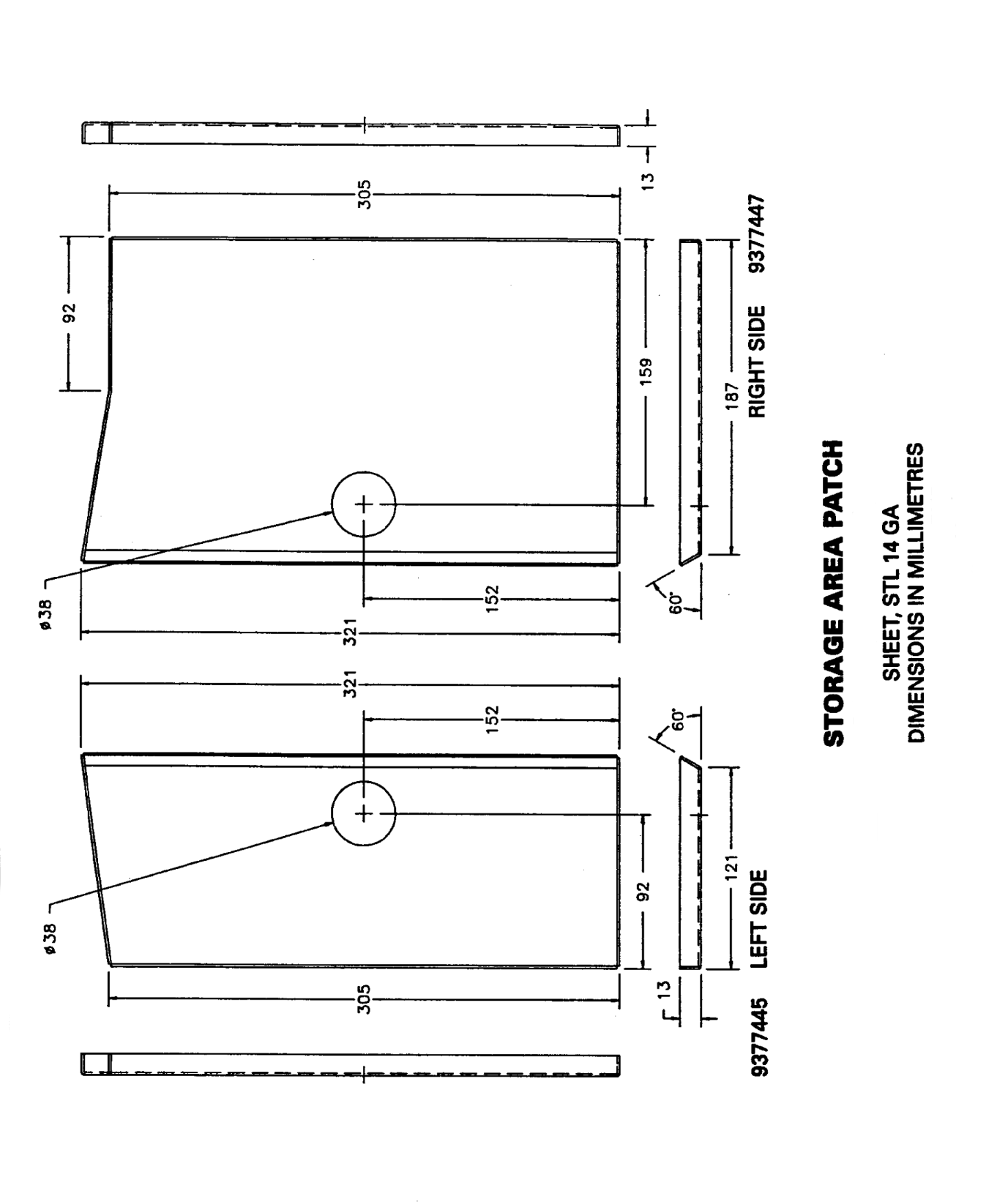 Figure 1-9 — Storage Area Patch Click image to enlarge.
 Figure 1-10 — Spare Tire Mounting Bracket Click image to enlarge.
 Figure 1-11 — Door Mount Brackets Click image to enlarge.
Part 2 — Description
Identification
1.Designation and/or NSN of items used in the repairs are shown in the illustrations and in the stores required list.
Locational Terms
2.Right and left sides of the vehicle are determined by viewing it from the rear, looking toward the front, unless otherwise specified.
Part 3 — Corrosion Repair and Control
Section 1 — Vehicle Repair
General
1.This section describes the corrosion repair procedures to be carried out on the Iltis Canadian.
Inspection
2.The corrosion repairs are to be carried out only as necessary. The extent of the repairs required will be determined by following the Inspection Procedures Annex A. The results of the inspection will be recorded on the Corrosion Damage - Inspection From Iltis, Figure A-1. This form is available as a DND 1987 (7-93) NSN 7530-21-911-0946 and is packaged in sets of 50. Forms are NCR coated in four copies. The actual repairs will be transcribed onto a request for maintenance services form; DND 1540 (8-89) NSN 7530-21-907-5046. Unit of Issue is one set (50 sets per package).
Strippping of Vehicle
3.Following the inspection, the vehicle shall be stripped as required. Other components are to be removed only as required to make repairs.
Preparation for Panelling
4.The metal surface onto which a panel is to be welding must be ground to pare metal extending 25 mm around the weld area. If coated, the panel must be ground 25 mm from the outer edge where weld is to be executed.
Welding Procedures
5.MIG or acetylene oxygen welding may be employed where welding is specified.
Operation Sequence
6.The sequence of operations in each corrosion repair structure is established by following the instructions in order of appearance and by numerical sequence of Ref. numbers with the Instructions & Hardware data.
Repair of Suspension Bump Stop Carrier (Left, Right)
See Figure 3-1-1.
 Figure 3-1-1 — Repair of Suspension Bump Stop Carrier (Left, Right) Click image to enlarge.
| Ref. | Instructions and Hardware |
|---|---|
| 1 | Inspect frame above suspension bump stop. |
| 2 | If crack is found, remove wheel and remove bump stop. |
| 3 | Grind out crack to 3 - 5 mm wide and 5 - 10 mm beyond visible end of crack. |
| 4 | Weld to fill slot. |
| 5 | Grind weld flush with surrounding metal. |
| 6 | Clean and apply primer (Item 1) to all bare metal surfaces. |
| 7 | Apply green paint (Item 2) over primer. |
| 8 | Reinstall bump stop and wheel. |
Repair of Fire Extinguisher Mount
See Figure 3-1-2.
 Figure 3-1-2 — Repair of Fire Extinguisher Mount Click image to enlarge.
| Ref. | Instructions and Hardware |
|---|---|
| 1 | Remove the bolts securing fire extinguisher to left rear well. |
| 2 | Sandblast any corroded areas. |
| 3 | Weld over any cracks around bolt holes with a full penetration butt weld. |
| 4 | Grind weld flush with surrounding metal. |
| 5 | Clean and apply primer (Item 1) to all bare metal surfaces. |
| 6 | Apply green paint (Item 2) over primer. |
| 7 | Replace fire extinguisher bracket and bolts. |
Repair of Flag Holders
See Figure 3-1-3.
 Figure 3-1-3 — Repair of Flag Holders Click image to enlarge.
| Ref. | Instructions and Hardware |
|---|---|
| 1 | Using an air chisel and grinder, remove the flag holders from the left and right fender. |
| 2 | Sandblast any corroded areas. |
| 3 | Weld on flag holders (Item 3) at original flag holder location using vertical fillet welds at mounting tabs. |
| 4 | Clean and apply primer (Item 1) to all bare metal surfaces. |
| 5 | Apply a small bead of Item 4 to any seams. |
Repair of Surface Corrosion
See Figure 3-1-4.
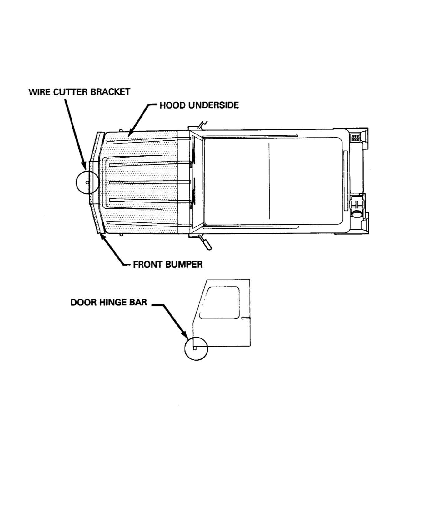 Figure 3-1-4 — Repair of Surface Corrosion Click image to enlarge.
| Ref. | Instructions and Hardware |
|---|---|
| 1 | For the following items, remove the part, sandblast any areas showing signs of corrosion, clean and apply primer (Item 1) to bare metal surfaces, and install the part. |
| a) Wire Cutter Bracket | |
| b) Door Hinge Bar (4) | |
| c) Front Bumper | |
| d) Hood Underside |
Repair of Side Panels
See Figure 3-1-5.
 Figure 3-1-5 — Repair of Side Panels Click image to enlarge.
| Ref. | Instructions and Hardware |
|---|---|
| 1 | Sandblast corroded areas at front and rear of left and right side panels. |
| 2 | Weld patch panel over perforated areas using the following parts: Item 5 - Front Left Item 6 - Front Right Item 7 - Rear Left Item 8 - Rear Right Weld around all edges using a 25 mm long weld on 75 mm centres. |
| 3 | Grind the weld flush with the panel. |
| 3 | Drill 6 - 13 mm dia. drain holes (3 per side) through underside of side panel 13 mm from outer edge at locations shown. |
| 4 | Clean and apply primer (Item 1) to all bare metal surfaces. |
| 5 | Apply a small bead of Item 4 to any seams. |
Repair of Front Floor and Fornt Body Mounts
See Figure 3-1-6.
 Figure 3-1-6 — Repair of Front Floor and Fornt Body Mounts Click image to enlarge.
| Ref. | Instructions and Hardware |
|---|---|
| 1 | Grind off the rearward facing protruding flange. |
| 2 | Sandblast corroded areas of front floor. |
| 3 | Cut out any weakened metal around any perforations. |
| 4 | Fabricate patches from 16 gauge SAE 1008 steel to overlap existing material by 10 - 25 mm. |
| 5 | Weld patches using 25 mm long fillets on 75 mm centres. |
| 6 | Clean and apply primer (Item 1) to all bare metal surfaces. |
| 7 | Apply a small bead of Item 4 to any seams. |
| 8 | Apply green paint (Item 2) over primer. |
Repair of Frame Rails
See Figure 3-1-7.
 Figure 3-1-7 — Repair of Frame Rails Click image to enlarge.
Repair of Rifle Mount Bracket
See Figure 3-1-8.
 Figure 3-1-8 — Repair of Rifle Mount Bracket Click image to enlarge.
| Ref. | Instructions and Hardware |
|---|---|
| 1 | Remove two bolts securing rifle mount clips to body. |
| 2 | Sandblast corroded areas of brackets. |
| 3 | Clean and apply primer (Item 1) to all bare metal surfaces. |
| 4 | Apply a small bead of Item 4 to any open seams. |
| 5 | Apply green paint (Item 2) over primer. |
| 6 | Replace bolts and rifle mount clips. |
Repair of Rear Fender Strut
See Figure 3-1-9.
 Figure 3-1-9 — Repair of Rear Fender Strut Click image to enlarge.
| Ref. | Instructions and Hardware |
|---|---|
| 1 | Remove wheel, and cut out existing strut using a chisel or grinder. |
| 2 | Weld new strut (Item 9) in same location as removed strut using a plug weld or fillet weld around edge as suitable. |
| 3 | Clean and apply primer (Item 1) to all bare metal surfaces. |
| 4 | Apply a small bead of Item 4 to any open seams. |
| 5 | Apply green paint (Item 2) over primer. |
Repair of Body Cracks
See Figure 3-1-10.
 Figure 3-1-10 — Repair of Body Cracks Click image to enlarge.
| Ref. | Instructions and Hardware |
|---|---|
| 1 | Drill a 3 mm hole at end of crack (side panel body cracks only). |
| 2 | Weld over crack and hole with full penetration butt weld. |
| 3 | Grind weld flush with surrounding metal. |
| 4 | Clean and apply primer (Item 1) to all bare metal surfaces. |
Repair of Jerry Can Holder
See Figure 3-1-11.
 Figure 3-1-11 — Repair of Jerry Can Holder Click image to enlarge.
| Ref. | Instructions and Hardware |
|---|---|
| 1 | Remove two bolts that attach licence plate to jerry can holder and remove licence plate. |
| 2 | Remove two screws that attach licence plate light to jerry can holder and remove licence plate light and cover. |
| 3 | Disconnect electrical harness from light and pull harness and harness clips from jerry can holder. |
| 4 | Remove the four screw and the wooden strips from the bottom of the jerry can holder. |
| 5 | Using 4 mm drill, drill out rivets securing strap to jerry can holder and remove strap. |
| 6 | Sandblast corroded areas on jerry can holder. |
| 7 | In the event of extensive corrosion damage or perforation, replace the jerry can holder with Item 10 by removing the nine bolts securing it to the body and discarding. |
| 8 | Clean and apply primer (Item 1) to all bare metal surfaces. |
| 9 | Apply green paint (Item 2) over primer. |
| 10 | Reassemble wooden strips and strap to holder, using rivets (Item 11) for strap. |
| 11 | Reassemble holder to body if required. |
| 12 | Reassemble licence plate and light. |
Repair of Rear Floor
See Figure 3-1-12.
 Figure 3-1-12 — Repair of Rear Floor Click image to enlarge.
| Ref. | Instructions and Hardware |
|---|---|
| 1 | Inspect rear floor. If only surface rust found, clean and apply primer (Item 1) to all bare metal surfaces. |
| 2 | Remove battery hold down plates, disconnect battery cables and remove batteries. |
| 3 | Disconnect emergency brake cables at equalizer and remove cables from bracket. |
| 4 | Cut out inner and outer rear floor and centre support as shown using an air chisel, abrasive cutoff wheel, torches and grinder as required. |
| 5 | Cut off portion of bracket that protrudes into battery compartment and discard. |
| 6 | Position rear floor plate (Item 13) and tack weld into place. |
| 7 | Insert cross support (Item 12) and centre support (Item 14) around existing brace and tack weld into place. |
| 8 | Fillet weld at all joints between new and existing panels with a 25 mm long fillet on 75 mm centres. |
| 9 | Clean and apply primer (Item 1) to all bare metal surfaces. |
| 10 | Apply a small bead of Item 4 to all unwelded seams. |
| 11 | Apply green paint (Item 2) over primer. |
| 12 | Place battery drip tray (Item 15) under each battery. (*M) |
| 13 | Reinstall batteries, drip trays, cables and hold down plates. |
Repair of Windshield Lower Frame
See Figure 3-1-13.
 Figure 3-1-13 — Repair of Windshield Lower Frame Click image to enlarge.
| Ref. | Instructions and Hardware |
|---|---|
| 1 | Inspect frame for rust. If rust is found, mask off windshield, sandblast rusted areas, clean and apply primer (Item 1) to all bare metal surfaces. Apply green paint (Item 2) over primer. |
| 2 | If perforation is present, unplug electrical connector at windshield wiper motor, remove six countersink screws securing windshield hinges to body and remove windshield. |
| 3 | Remove countersink screws at lower corners of windshield, pull frame off windshield, discard and replace with item 16. Clean and apply primer (Item 1) to replacement frame prior to installation. |
| 4 | If minor perforation is present, remove countersink screws at lower corners of windshield, and pull lower frame off windshield. |
| 5 | Fabricate patches from 16 gauge SAE 1008 steel to overlap existing material by 10 - 25 mm. |
| 6 | Weld patches to frame using a continuous fillet weld. |
| 7 | Grind weld flush with patch. |
| 8 | Clean and apply primer (Item 1) to all bare metal surfaces. |
| 9 | Apply green paint (Item 2) over primer. |
| 10 | Push frame onto windshield and install countersunk screws at windshield corners. |
| 11 | Reinstall windshield with six countersunk screws and plug in electrical connector at windshield motor. |
Repair of Rear Seat Front Mount, Hinges and Latches
See Figure 3-1-14.
 Figure 3-1-14 — Repair of Rear Seat Front Mount, Hinges and Latches Click image to enlarge.
| Ref. | Instructions and Hardware |
|---|---|
| 1 | Unlatch seat backs and pivot seats forward. |
| 2 | Remove four bolts securing rear seat pans to crossmembers and remove seats. |
| 3 | Drill out retainer nuts on existing crossmember, using an 8 mm drill. |
| 4 | Sandblast any corroded areas on crossmember and apply primer (Item 1) to all bare metal surfaces. |
| 5 | Place cap (Item 17) over crossmember and weld to crossmember using 25 mm long fillet welds at 75 mm centres. |
| 6 | Unsnap seat covers and remove seat covers and cushions from seat backs and bases. |
| 7 | On rear seat latches, add fillet weld as shown. |
| 8 | Remove circlip from existing latch pivot pin and remove existing pin by pushing out with pin (Item 18). |
| 9 | Fully inset pin (Item 18) into latch and secure with washer (Item 19) and cotter pin (Item 20). |
| 10 | Inspect hinges on rear seat bases and grind off from seat bases any hinges that have broken, loose or seized pivot pins. Hinges should be replaced in pairs. If one hinge is defective, both hinges on the seat should be replaced. |
| 11 | Assemble seat hinges as shown in Figure 1-7 (Items 21, 22, 23 and 25 Right Hand, Items 21, 22, 24 and 25 Left Hand). |
| 12 | Weld new hinges (Items 21, 22, 23, 24 LH, RH) onto seat bases. |
| 13 | Clean and apply primer (Item 1) to all bare metal surfaces. |
| 14 | Apply a small bead of Item 4 to any open seams or crossmember. |
| 15 | Apply green paint (Item 2) over primer. |
| 16 | Reinstall seat cushions and seat covers to seat backs and seat bases, and bot seat plans to crossmember. |
Repair of Storage Areas (Left, Right)
See Figure 3-1-15.
 Figure 3-1-15 — Repair of Storage Areas (Left, Right) Click image to enlarge.
| Ref. | Instructions and Hardware |
|---|---|
| 1 | Remove hole plugs from left and right storage compartments. |
| 2 | Sandblast corroded areas of storage compartments. |
| 3 | Cut out horizontal surfaces of lower storage compartments with grinder or torch if extensive surface corrosion or perforation is present and weld in patch (Item 27, left, Item 28, right), using a 25 mm fillet on 75 mm centres. |
| 4 | Clean and apply primer (Item 1) to all bare metal surfaces. |
| 5 | Apply a small bead of Item 4 to all unwelded seams from above and below panel. |
| 6 | Apply green paint (Item 2) over primer. |
| 7 | Replace hole plugs. |
Repair of Body Support (Left, Right)
See Figure 3-1-16.
 Figure 3-1-16 — Repair of Body Support (Left, Right) Click image to enlarge.
| Ref. | Instructions and Hardware |
|---|---|
| 1 | Inspect bracket for cracks in area of arrow. |
| 2 | If crack is found, grind out crack to a width of 3 - 5 mm and extending 20 mm beyond end of crack. |
| 3 | Weld over slot to fill with a convex surface. |
| 4 | Clean and apply primer (Item 1) to all bare metal surfaces. |
| 5 | Apply green paint (Item 2) over primer. |
Repair of Spare Tire Bracket
See Figure 3-1-17.
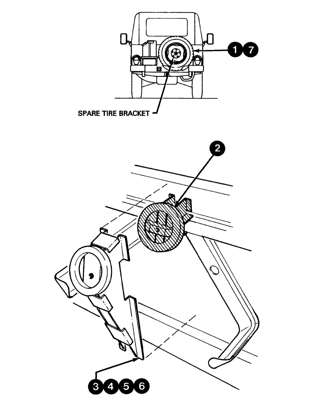 Figure 3-1-17 — Repair of Spare Tire Bracket Click image to enlarge.
| Ref. | Instructions and Hardware |
|---|---|
| 1 | Remove spare tire mounting bolt and spare tire. |
| 2 | Cut away existing spare tire bracket using abrasive cut off wheel, torch or grinder. Do not cut stiffener channels on body. |
| 3 | Locate new bracket (Item 29) over stiffeners. Weld in place using continuous fillet welds. |
| 4 | Clean and apply primer (Item 1) to all bare metal surfaces. |
| 5 | Apply a small bead of Item 4 to all unwelded seams. |
| 6 | Apply green paint (Item 2) over primer. |
| 7 | Replace spare tire and mounting stud. |
Repair of Rear Body Mount Brackets
See Figure 3-1-18.
 Figure 3-1-18 — Repair of Rear Body Mount Brackets Click image to enlarge.
| Ref. | Instructions and Hardware |
|---|---|
| 1 | Remove nuts and washers from rear body mount rubber upper studs. |
| 2 | Sandblast horizontal surfaces of rear body mounts. NOTE — Repair of left side body mounts may require removal of fuel tank, as per |C-30-108-000/MP-001 Section 18 and 19. |
| 3 | Cut out horizontal surfaces of rear body mounts using a grinder if severe surface rust or perforation is found. |
| 4 | Weld in replacement body mounts (Item 25) using a stitch weld on upper edges and continuous weld on lower edges. |
| 5 | Drill 2-13 mm drain holes (one per side) as shown. |
| 6 | Clean and apply primer (Item 1) to all bare metal surfaces. |
| 7 | Apply a small bead of Item 4 to all unwelded seams between body mount and body. |
| 8 | Apply green paint (Item 2) over primer. |
Repair of Front Fender
See Figure 3-1-19.
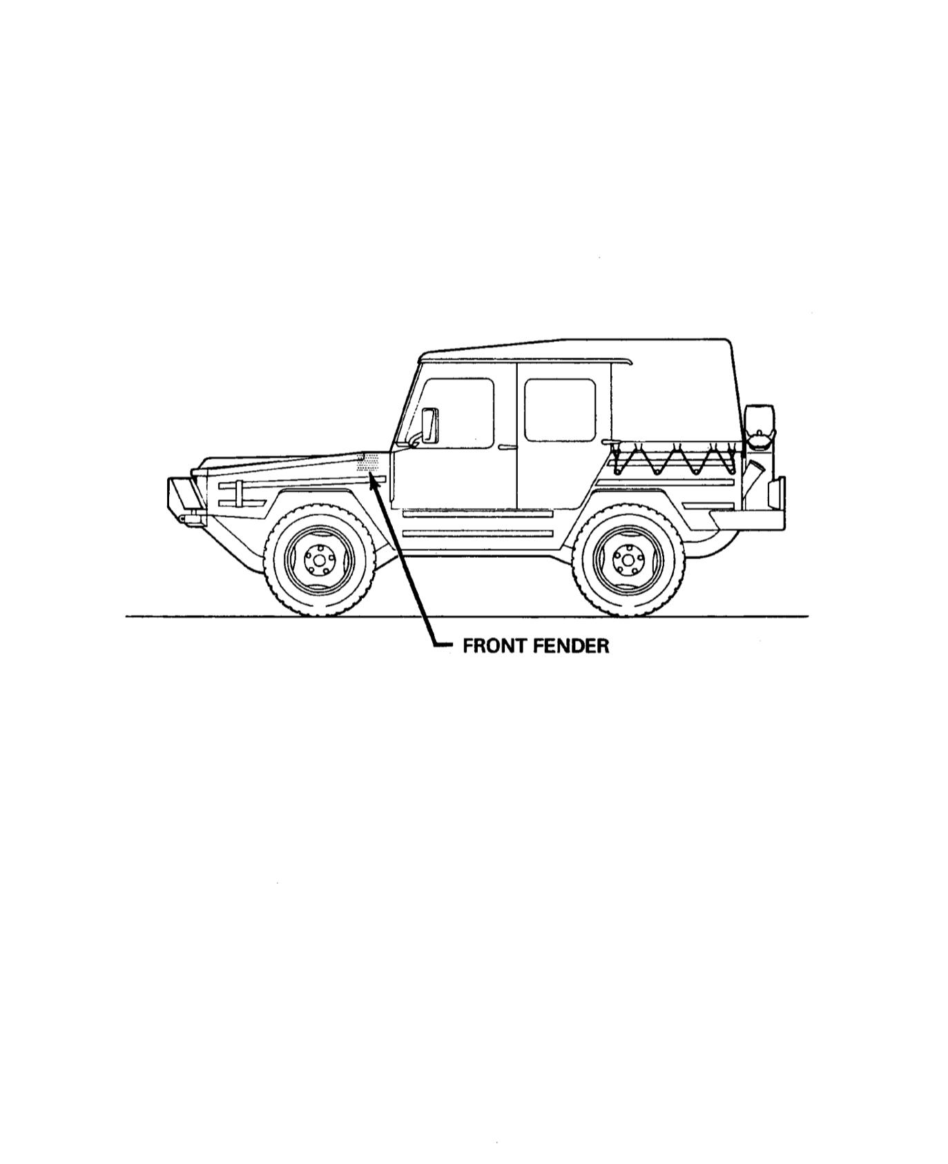 Figure 3-1-19 — Repair of Front Fender Click image to enlarge.
| Ref. | Instructions and Hardware |
|---|---|
| 1 | Sandblast corroded areas. |
| 2 | Drill out end of any cracks with 3 mm dia hole. |
| 3 | Weld over any cracks with a full penetration butt weld from the outside. |
| 4 | Grind the weld flush with the surrounding metal. |
| 5 | Clean and apply primer (Item 1) to all bare metal surfaces. |
Repair of Control Arm Bracket (Front, Rear)
See Figure 3-1-20.
 Figure 3-1-20 — Repair of Control Arm Bracket (Front, Rear) Click image to enlarge.
| Ref. | Instructions and Hardware |
|---|---|
| 1 | Scrape away caulking from joint between control arm bracket and frame at the front and rear of each bracket. |
| 2 | Sandblast any corrosion found. |
| 3 | Clean and apply primer (Item 1) to all bare metal surfaces. |
| 4 | Apply a small bead of Item 4 to all open seams. |
| 5 | Apply green paint (Item 2) over primer. |
Repair of Rear Floor Crossmember
See Figure 3-1-21.
 Figure 3-1-21 — Repair of Rear Floor Crossmember Click image to enlarge.
| Ref. | Instructions and Hardware |
|---|---|
| 1 | Remove bolts and screws securing rear floor plates to body. |
| 2 | Remove floor plates (5). |
| 3 | Remove attaching hardware and remove rails (4). |
| 4 | Remove attaching hardware and remove rear floor cover. |
| 5 | Inspect crossmember at front of opening in area over the differential. If no cracks are found, replace the cover, rails and plates in reverse order of removal. |
| 6 | If cracks are found, clean around crack with wire brush and weld over crack with full penetration butt weld. Ensure that the fuel tank is covered to protect from sparks when grinding or welding. |
| 7 | Drill 3-8 mm diameter drain holes through rear floor at locations shown. |
| 8 | Clean and apply primer (Item 1) to all bare metal surfaces. |
| 9 | Apply green paint (Item 2) over primer. |
| 10 | Replace the cover, rails and plates in reverse order of removal. |
Repair of Door Mounts (Front, Rear)
See Figure 3-1-22.
 Figure 3-1-22 — Repair of Door Mounts (Front, Rear) Click image to enlarge.
| Ref. | Instructions and Hardware |
|---|---|
| 1 | Remove plastic inserts (Item 37) from door mount bracket. |
| 2 | Mark vertical centre line of bracket below bracket and horizontal height at side of bracket using a permanent marker or scriber. |
| 3 | Grind off bracket. |
| 4 | Sandblast any corrosion without obscuring marks. |
| 5 | Weld on new brackets (Item 30 - front, Item 31 rear) using continuous fillet weld, locating on same centre line as old brackets. |
| 6 | Grind weld flush with surrounding metal. |
| 7 | Clean and apply primer (Item 1) to all bare metal surfaces. |
| 8 | Replace plastic inserts (Item 37). |
Repair of Overlapping Panel Separation
See Figure 3-1-23.
 Figure 3-1-23 — Repair of Overlapping Panel Separation Click image to enlarge.
| Ref. | Instructions and Hardware |
|---|---|
| 1 | For the following areas, use the procedure below to repair corrosion damage. a) front door water deflector b) front floor underside near body mount |
| 2 | Sandblast corroded areas. Fabricate patches from 16 gauge SAE 1008 steel to overlap existing material by 10 - 25 mm to cover any perforation damage. |
| 3 | Weld patches using a continuous fillet weld. |
| 4 | Grind weld flush with surrounding metal if weld is on visible surface of vehicle. |
| 5 | Clean and apply primer (Item 1) to all bare metal surfaces. |
| 6 | Apply a small bead of Item 4 to all unwelded seams. |
Repair of Wiring Harness
See Figure 3-1-24.
 Figure 3-1-24 — Repair of Wiring Harness Click image to enlarge.
| Ref. | Instructions and Hardware |
|---|---|
| 1 | Remove hose clamp from gas tank filler neck and pull back filler neck hose. |
| 2 | Move wire harness from under filler neck to over filler neck. |
| 3 | Push filler neck hose over filler neck and install hose clamp. |
| 4 | Secure wire harness on top of filler neck and hose with a tie wrap (Item 32). |
Section 2 — Rustproofing
General
1.Complete rustproofing is mandatory.
2.Apply a coating of rustproofing (Item 33) under hood and underside of vehicle.
3.The product used shall be an oil spray specifically formulated for vehicle corrosion protection, having the following properties:
- Mineral oil base with a minimum viscosity of SAE 10;
- contain rust and oxidation inhibitors;
- moisture repelling and displacing;
- creeping and self-healing;
- low solvent content;
- compatible with other materials;
- contains no used oil, fuel oil or detergent additives; and
- non-toxic.
4.The contractor’s product shall also meet the following criteria:
- The product shall be certified by an independent test laboratory as capable of passing an eight (8) hour ASTM B117 salt spray endurance test;
- the product should be Krown, Rust Check or Authority approved equivalent.
Application Procedure
1.Any accumulated mud must be removed.
2.The applied material shall not interfere with the efficient functioning of any mechanical or electrical component of the vehicle, nor shall it block any drainage holes or passages.
3.The application shall include but not be limited to: the underside of fenders and hood, enclosed and boxed-in sections, seams moulding, crevices, weld points, vehicle underside, exposed exterior brackets and internal parts of vehicle’s tubular frame.
4.The Contractor shall drill holes if required or remove plugs from previously drilled holes and apply the prevention treatment as required.
5.All holes drilled to facilitate the application of the undercoating material shall be 1/2“ or less in diameter, and shall be sealed with plastic or rubber seal caps.
6.After the treatment a complete visual inspection shall be made to ensure that all specified areas have been treated. At least one spot check will be completed on each vehicle eg, at light assembly or panel etc., and visually inspecting to ensure complete coverage by treatment.
7.The vehicle shall be left in a clean and undamaged condition after the completion of the undercoating. No over-spray or excess material shall remain on any visible portion of the interior or exterior of the vehicle.
Section 3 — Painting

General
1.No complete painting is authorized. Only repaired/replaced components will be painted.
Camouflage Paint Patterns
2.Follow the colours and patterns identified in Figure 3-3-1 to paint the camouflage disruptive pattern. The paint colours must be applied and feathered to conform with the pattern of the vehicle. The infrared reflective camouflage paint is used on exterior surfaces of steel or aluminum bodies as a top coat and can be applied with a spray-gun, brush or roller. On bare surfaces apply the proper primer before painting. Do not dry the paint above 122 degrees celsius. Do not apply paint below a temperature of 5 degrees celsius.
Paint Legend
3.The paint legend shows the colours to be used in each figure location:
4.Apply a coating of stoneguard (Item 34) over interior surfaces of storage compartments and repaired areas of front and rear floors.
CAUTION — All Iltis vehicles are painted with Chemical Agent Resistant Coating (CARC). The dust and vapours generated when welding or grinding on surfaces painted with CARC may be hazardous.
Section 4 — Special Equipment
| Item | NSN | DWG./Part No | NSCM | Description | Qty |
|---|---|---|---|---|---|
| 1 | 5130-21-844-4513 | MC121A2KIT | 05563 | Cutter, impact, pneumatic hammer | 1 |
| 2 | 5120-00-221-1597 | AT508 | 00784 | Forceps, sheet holder | 1 |
| 3 | 3433-21-646-0208 | DECMM361 | 35898 | Torch Outfit, cutting and welding | 1 |
| 4 | 5130-21-108-8457 | G0900 | 05563 | Sander, oscillating pad, pneumatic | 1 |
| 5 | PT-31XL | 55019 | Cutting Torch, Plasma arc | 1 | |
| 6 | Commercial | Sand blasting equipment | 1 | ||
| 7 | Commercial | Rustproofing Eqpt. | 1 |
Figure 3-4-1 — Special Equipment Required Click image to enlarge.
Section 4 — Grinding of Alternator Adjuster
See Figure 3-5-1.
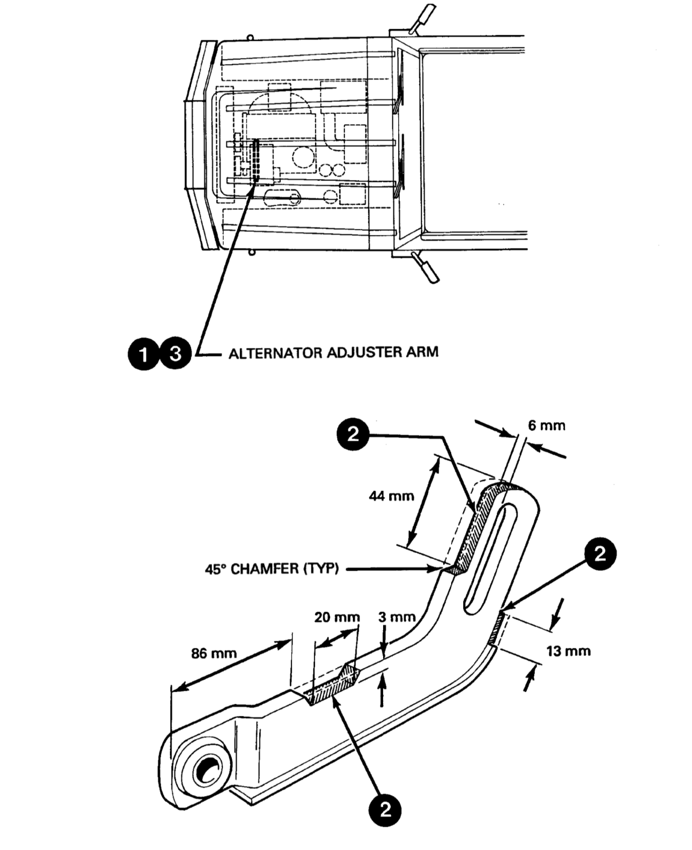 Figure 3-5-1 — Grinding of Alternator Adjuster Click image to enlarge.
| Ref. | Instructions and Hardware |
|---|---|
| 1 | Remove the two bolts securing the alternator adjuster to engine assembly. |
| 2 | Remove the areas shown on the adjuster with a disc grinder. This increases the range of adjustment by about 14 mm. |
| 3 | Replace the adjuster and check the alternator drive belt tension as described in C-30-108-000/MP-001, Section 5, Para 23d. |
Annex A
Instructions
Preparation
1.The vehicles shall be prepared for inspection by:
- removing stowed equipment from interior;
- removal of floor mats; and
- thorough cleaning.
Inspection
2.The vehicle will be inspected for evidence of corrosion damage beginning at the left front corner and proceeding counter clockwise around the vehicle to the right front.
3.The inspection will be visual supported by probing with a sharp pointed probe (Ice Pick). Where there is visual evidence of corrosion or corrosion is suspected the area will be probed using hand pressure on an “ice pick”.
Classification
4.An AREA/ITEM will be considered serviceable if there is no evidence of corrosion.
5.An AREA/ITEM will be refinished if surface corrosion is present but cannot be penetrated with hand pressure on “ice pick”.
6.An AREA/ITEM will be repaired using the applicable procedures in CFTO C-30-108-000/VC-001 if:
- there is visible evidence of corrosion penetration within AREA/ITEM or if; and
- any point within the AREA/ITEM can be penetrated with hand pressure on “ice pick”.
7.An AREA/ITEM will be replaced if the estimated cost of repair exceeds the replacement cost using labour times as detailed in CFTO C-30-108-000/NP-000.
Recording
8.CORROSION DAMAGE - INSPECTION FORM. Figures on reverse will be completed for each Iltis Canadian vehicle. These forms will be retained with vehicles CF 1020 record.
Special Instructions
9.A copy of the inspection form will be made noting the patches that have been installed.
10.Should the vehicle require repairs not noted on the reverse of this form, the location of the repair(s) is to be indicated in the appropriate figure and the problems are to be detailed in the blank comment boxes.
| VEHICLE CF | VEHICLE ECC | DATE |
|---|
| DESCRIPTION | DESCRIPTION | ||||
|---|---|---|---|---|---|
| 1 | Bumper/Grill, Front | 12 | Body Mount, Right Front | ||
| 2 | Hood | 13 | Body Mount, Right Rear | ||
| 3 | Panel, Front, Left | 14 | Panel, Side, Forward Right | ||
| 4 | Panel, Side, Forward Left | 15 | Panel, Front, Right | ||
| 5 | Body Mount, Left Front | 16 | Storage Area, Right | ||
| 6 | Body Mount, Left Rear | 17 | Storage Area, Left | ||
| 7 | Panel, Side Rear Left | 18 | Floor, Front, Left | ||
| 8 | Support, Jerry Can | 19 | Floor, Front, Right | ||
| 9 | Support, Spare Tire | 20 | Floor, Battery Storage | ||
| 10 | Panel, Rear | 21 | Mounts, Door | ||
| 11 | Panel, Side Rear Right |

Figure A-1 — Corrosion - Damage Inspection Form Iltis Canadian Click image to enlarge.