
C-30-108-000/MP-002 - Overhaul Manual

1986-12-05247 Pages
For other Canadian Forces Technical Order (CFTO) documents, see Iltis-related Canadian Forces Technical Order Documents.

C-30-108-000/MP-002
Overhaul Manual
For Truck, Utility, Light, 4 x 4, Military Design, Iltis Canadian Series
Issued on Authority of the Chief of the Defence Staff
OPI: DSVEM 2
1986-12-05

WARNING — All parts on the Iltis Canadian Series are dimensioned in the metric system. During any maintenance procedures, all replacement fasteners must have the same measurement and strength as those removed. (Numbers on the heads of metric bolts and on the surfaces of metric nuts indicate their strength). Mismatched or incorrect fasteners may result in personal injury, damage or malfunction of components. Therefore, fasteners removed from the engine should be saved for re-use in the same location where possible. When fasteners are unsatisfactory for re-use, care should be taken to select a replacement that matches the original.
Part 1 — General Description
Section 1 — General
Scope
1.This manual contains overhaul procedures for the engine, transaxle and rear differential for the Truck, Utility, Light 4×4 Military Design, Iltis Canadian Series at third and fourth line maintenance units. Information on component maintenance and repair is provided in CFTO C-30-108-000/MP-001.
Authority
2.All correspondence concerning this manual should be directed to:
National Defence Headquarters
Ottawa, Canada K1A OK2
Attention: DSVEM 2
Types of Overhaul
3.Types of information in this manual include removal, disassembly, cleaning, inspection, measurements, repair, adjustments and assembly.
Manual Organization
4.The manual is organized into the following parts:
Section 2 — General Overhaul Procedures
Introduction
1.To perform a major overhaul or other extensive repairs, the complete assembly should be mounted on an overhaul stand and the various assemblies removed.
2.Parts removed from an individual assembly should be kept together to be available for inspection and reassembly to the same assembly. Those items having machined faces, which might be easily damaged by steel or concrete, should be stored on suitable wooden racks or blocks, or on a separate dolly.
3.For inspection, repair and overhaul of all engine components, including the coolant pump, alternator, starter, oil pan and oil pump,carburetor and distributor, refer to "Truck, Utility, Light, 4x4 Military Design, Iltis Canadian Series, Maintenance Manual", CFTO C-30-108-000/MP-001.
4.When a decision to use a new component is made, the following general factors should be considered:
- degree of wear of the old component;
- time required for reconditioning an old component compared with the cost of a new component;
- component deterioration (usually electrical) due to length of service time and operating environment;
- hours in service; and
- the next overhaul period.
Cleaning
5.General — After each subassembly is removed and disassembled, the individual parts should be cleaned. Thorough cleaning of each part is absolutely necessary before it can be satisfactorily inspected. Before removing any of the subassemblies from the engine (but after removal of the electrical equipment), the exterior of the engine should be thoroughly cleaned.
6.Steam Cleaning — A steam cleaner can be used to remove heavy accumulations of grease and dirt from the exterior of the engine and its subassemblies after removal of the electrical equipment.
7.Solvent Tank Cleaning — A tank of sufficient size to accommodate the largest part that will require cleaning (usually the cylinder block) should be provided and provisions made to heat the cleaning solvent between 82 and 93°C.
8.Fill the tank with a commercial heavy duty solvent and heat between 82 and 93°C. Lower large parts directly into the tank with a hoist. Place small parts in a wire mesh basket and lower them into the tank. Immerse the parts long enough to loosen all grease and dirt.
9.Rinsing Bath — Provide another tank of similar size to the solvent cleaning tank, containing hot water for rinsing the parts.
10.Drying — Parts may be dried with compressed air. However, the heat transferred to the part from the hot tanks will frequently completely dry the parts without the use of compressed air.
11.Machined Surface Cleaning — Make sure that mating surfaces are thoroughly clean and free from such foreign matter as gasket debris.
12.Rust Preventive — If parts are not used immediately after cleaning, dip them in a suitable rust preventive compound. Remove the rust preventive compound before installing the parts.
Inspection
13.The purpose of parts inspection is to deter mine which parts can be used and which must be replaced. Although the overhaul specifications given throughout the manual will aid in determining which parts should be replaced, considerable judgement must be exercised by the inspector.
14.Many service replacement parts are available in various undersizes or oversizes as well as standard sizes. Also, service kits for reconditioning certain parts, and service sets, which include all of the parts necessary to complete a particular repair job, are available.
15.In addition to measuring the used parts after cleaning, parts shall be carefully inspected for cracks, scoring, chipping and other defects.
Assembly
16.Following cleaning and inspection, use new parts as determined by the inspection.
17.Use of proper equipment and tools makes the job progress faster and produces better results. A suitable working space with proper lighting is essential.
18.Keep working space, equipment, tools, assemblies and parts clean at all times. The area where assembly takes place should, if possible, be away from the disassembly and cleaning operation. Any machining operation should be as far as possible from the assembly area.
19.After removal and cleaning, particular attention should be paid to the storage of parts and subassemblies. If there is any doubt as to the cleanliness of stored parts, they should be cleaned before use.
20.All assembly operations and measurements require great care and absolute cleanliness if accurate results are to be obtained.
Work Safety
21.The following safety precautions shall be strictly observed:
- When using compressed air to clean a component, use a safe amount. Too high an air pressure could result in personal injury or damage to a component.
- Avoid the use of carbon tetrachloride as a cleaning agent because of the harmful vapour that it releases. Use perchlorethylene or trichlorethylene. However, while less toxic than other chlorinated solvents, use these cleaning agents with caution. Be sure the work area is adequately ventilated and use protective gloves, goggles or face shield and apron.
- Exercise caution against burns when using oxalic acid to clean the cooling passages of the engine.
- Always wear protective gear such as safety glasses, safety shoes and hard hat to provide adequate protection when working under hazardous conditions.
- When lifting an assembly, make sure the lifting device is fastened securely. Be sure the item to be lifted does not exceed the capacity of the lifting device.
- Use caution when operating power tools.
Part 2 — Engine
Section 1 — Disassembly
Clutch Pressure Plate
1.Removal — Remove the six socket head screws from the clutch pressure plate and pull the pressure plate and clutch disc away from the flywheel.
Flywheel

Figure 2-1-1 — Tool B 183 012 361 InstalledClick image to enlarge.
2.Removal — To remove, proceed as follows:
- Install tool B 183 012 361 to prevent the flywheel from turning, see Figure 2-1-1, and remove the six cap screws from the flywheel.
- Remove the flywheel from the crankshaft.
NOTE — It is not necessary to scribe the flywheel prior to removal. The flywheel will fit onto the crankshaft in one position only.
Intermediate Plate
3.Removal — Remove the intermediate plate and mount the engine on a stand.
Carburetor
4.Removal — To remove, proceed as follows:
- Remove the vacuum advance hose.
- Remove the four cap screws from the carburetor and remove the carburetor.
Intake Manifold

Figure 2-1-2 — Exhaust Manifold BracketClick image to enlarge.
5.Removal — To remove, proceed as follows:
- Remove the two coolant hoses from the manifold.
- Remove the cap screw that secures the intake manifold to the exhaust manifold bracket, see Figure 2-1-2.
- Loosen the nut on the exhaust manifold bracket stud. Remove the bracket.
- Remove the six socket head cap screws from the manifold and remove the manifold and gasket.
Exhaust Manifold
6.Removal — To remove, proceed as follows:
- Remove the eight nuts and flat washers from the manifold.
- Remove the manifold and four exhaust gaskets.
Alternator
7.Removal — To remove, proceed as follows:
- Prior to removing the drive belts, loosen the coolant pump and crankshaft pulley cap screws.
- Remove the alternator adjusting bolt and flat washer and remove the drive belts.
- Remove the alternator adjusting arm.
- Remove the plug from the timing belt upper cover and, using a 6 mm hex head socket, hold the mounting bolt and remove the nut.
- Support the alternator and withdraw the mounting bolt.
- Remove the alternator from the bracket.
Coolant Pump
8.Removal — To remove, proceed as follows:
- Remove the bolt, nut and lock washer that secure the timing belt lower cover to the coolant pump.
- Loosen the hose clamps that secure the two coolant hoses to the pump and disconnect the hoses.
- Remove the four cap screws from the coolant pump and remove the pump.
Distributor

Figure 2-1-3 — Distributor Locking CollarClick image to enlarge.
9.Removal — To remove, proceed as follows:
- Disconnect the four spark plug high tension cables from the spark plugs.
- Remove the cap screw from the distributor locking collar, see Figure 2-1-3.
- Remove the distributor.
Engine Mounting Brackets
10.Removal — Remove the cap screws and washers from the brackets and remove the brackets.
Oil Filter Housing
11.Removal — To remove, proceed as follows:
- Using an oil filter wrench, remove the oil filter.
- Remove the oil temperature sending unit.
- Remove the three socket head screws and flat washers from the oil filter housing and remove the housing and gasket.
Crankshaft Pulley
12.Removal — Remove the four socket head screws from the pulley and remove the pulley.
Timing Belt

Figure 2-1-4 — Intermediate Shaft Seal and CarrierClick image to enlarge.
13.Removal — To remove, proceed as follows:
- Remove the upper and lower timing belt covers.
- Loosen the locking nut on the timing belt tensioner. Turn the tensioner counter-clockwise and remove the timing belt.
Intermediate Shaft and Sprocket

Figure 2-1-5 — Intermediate ShaftClick image to enlarge.
14.Removal — To remove, proceed as follows:
- Remove the intermediate shaft sprocket.
- Remove the two securing cap screws and remove the intermediate shaft oil seal and seal carrier, see Figure 2-1-4.
- Carefully, so as not to damage the bearings with the distributor drive gear or fuel pump eccentric, pull the intermediate shaft from the engine block, see Figure 2-1-5.
Timing Belt Rear Plate
15.Removal — To remove, proceed as follows:
- Remove the cap screws from the timing belt rear plate.
- Remove the crankshaft timing sprocket.
- Remove the cap screw and nut that secure the plate to the front of the engine block and remove the plate and front alternator bracket.
Alternator Bracket (Rear)
16.Removal — Remove the two cap screws and washers from the bracket and remove the bracket.
Valve Cover
17.Removal — To remove, proceed as follows:
- Remove the accelerator cable mounting bracket and two spark plug wire securing brackets and washers from the left side of the valve cover.
- Remove the cover reinforcement bars from both sides.
- Remove the valve cover.
- Remove the gasket from the cover.
- Remove the rubber half seal from the front camshaft bearing cap.
- Remove the rubber seal plug from the rear of the head.
Cylinder Head

Figure 2-1-6 — Cylinder Head Bolt Tightening SequenceClick image to enlarge.
18.Removal — To remove, proceed as follows:
- Starting at the front and rear of the cylinder head and working toward the centre, loosen a little at a time, the cylinder head securing bolts in the reverse sequence to that shown in Figure 2-1-6. Remove the bolts and flat washers.
- Remove the cylinder head. If the head will not move, insert the handle of a hammer into an exhaust port and pry the head loose.
- Remove the cylinder head gasket and, using either a plastic scraper or solvent, remove the pieces of gasket that are stuck to the cylinder head and engine block. Do not use a metal scraper or wire brush.
Oil Pan and Gasket
19.Removal — To remove, proceed as follows:
- Remove the drain plug from the oil pan and drain the oil into a suitable container.
- Remove the twenty oil pan securing cap screws and flat washers.
- Loosen the oil pan and remove.
- Remove the oil pan gasket from the engine block.
Oil Pump
20.Removal — To remove, proceed as follows:
- Remove the two cap screws and flat washers from the bottom of the oil pump housing.
- Withdraw the oil pump drive shaft from the engine block.
Piston Assemblies

Figure 2-1-7 — Removal of Top Cylinder RidgesClick image to enlarge.
21.Removal — To remove, proceed as follows:
- Mark the tops of unmarked pistons with a piston number and an arrow pointing towards the front of the engine, so that the pistons will be reassembled in the same order and direction.
- Remove the connecting rod nuts and connecting rod caps.
CAUTION — If the engine block has any top cylinder ridges, remove them with a ridge reamer before removing the pistons, as the piston rings and pistons could be damaged during removal, see Figure 2-1-7.
- Using a hammer handle, push the piston/connecting rod assembly away from the crankshaft and through the top of the cylinder.
- Immediately after each piston/connecting rod assembly is removed, mark the cylinder number on both the rod cap and the connecting rod, on the intermediate shaft side.

Figure 2-1-8 — Removal of Piston Pin CirclipClick image to enlarge.

Figure 2-1-9 — Removal of Piston PinClick image to enlarge.
22.Disassembly — To disassemble, proceed as follows:
- Using needle-nosed pliers or a punch as a lever, remove the piston pin circlips from both ends of each piston pin, see Figure 2-1-8.
- Using tool VW 207c, press the pins out and remove the pistons from the connecting rods, see Figure 2-1-9.
NOTE — If the piston pin is difficult to remove, heat the piston in oil to a temperature of 60°C. Correct pin fit should require only a light push to remove the pin from a heated piston.
Crankshaft

Figure 2-1-10 — Front Crankshaft Seal CarrierClick image to enlarge.
23.Removal — To remove, proceed as follows:
- Remove the six securing cap screws and washers and remove the rear crankshaft seal carrier.
- Remove the three securing cap screws and washers and remove the front crankshaft seal carrier, see Figure 2-1-10.
- Remove the securing bolts from the five main bearing caps and remove the caps and bearings.
- Remove the crankshaft.
NOTE — The main bearing caps are factory-numbered to ensure correct installation. If the bearings are to be reused, mark the bearing numbers on the backs of the bearing shells as they are removed and note the upper and lower positions. The centre bearing is a flanged thrust bearing.
- Remove the bearing shells from the main bearing saddles.
Crankshaft Pilot Bearing
24.Removal — Using extractor 10-202, remove the pilot bearing from the crankshaft.
Block Heater
25.Removal — To remove, proceed as follows:
- Loosen and unscrew the heater retaining screw to the limit of its travel.
- Withdraw the heater from the frost plug opening of the cylinder block.
Cylinder Head Coolant Outlet Connector (LH Side)
26.Removal — Remove the three capscrews and washers from the cylinder head and remove the connector and gasket.
Cylinder Head Heater Coolant Connector (Rear)
27.Removal — Remove the two capscrews and washers from the cylinder head and remove the connector and gasket. Remove and identify the sending units.
Section 2 — Cleaning and Inspection
Cylinder Block

Figure 2-2-1 — Checking Cylinder Block for FlatnessClick image to enlarge.
1.Flatness Check — To check, proceed as follows:
- Ensure the block is clean.
- Check the top of the block for flatness through the centre of bores with an accurate straight edge and feeler gauge, see Figure 2-2-1. The surface must not vary more than 0.10 mm longitudinally. If the flatness is not within the above limits, the cylinder block must be resurfaced. The maximum amount that can be cut from an engine block is 0.25 mm. The engine rebuild plate must include the total amount which has been cut from the block.
- Check and clean all bolt hole threads and stud threads. Repair as necessary and lubricate.

Figure 2-2-2 — Checking Cylinder Diameter and Degree of WearClick image to enlarge.
2.Cylinder Bore — To check, proceed as follows:
- Using a cylinder bore gauge, determine the cylinder diameter and degree of wear. Record the readings, see Figure 2-2-2.
NOTE — When checking the cylinder bores, remove the cylinder block from the engine stand, take measurements at three points in each cylinder and at right angles to one another. The first measurement should be made 10 mm from the top. The second measurement should be in the middle of the cylinder, and the third 10 mm from the bottom. Take one set of measurements, first in one direction (e.g., across the width of the engine) and then take a second set of measurements in another direction (e.g., in line with the crankshaft).
- Minor variations in cylinder diameter can be corrected by honing. If there is scoring or there are variations of 0.05 mm or more between the measurements in any one cylinder, or a cylinder is worn to more than 0.08 mm over the original or oversized bore, all the cylinders must be rebored and honed to accept the next larger-size piston.
| Size | Piston Marking | Cylnder Bore Honing Diameter |
|---|---|---|
| Original Diameter | 79.50 mm | 79.53 mm |
| 1st Oversize | 79.75 mm | 79.78 mm |
| 2nd Oversize | 80.00 mm | 80.03 mm |
| 3rd Oversize | 80.50 mm | 80.53 mm |
Figure 2-2-3 — Cylinder Bore Honing Measurements
- Record the largest bore diameter measurement obtained for each cylinder.
- Compare these measurements with the honing measurements, see Figure 2-2-3.
NOTE — Rebored cylinders must be honed to obtain a clearance of 0.03 mm between the piston and the cylinder wall.

Figure 2-2-4 — Cylinder Wall Glaze RemovedClick image to enlarge.
- Compute the piston clearance between the original pistons and their respective cylinders. Subtract the diameter of the piston, see para. 3, from the maximum diameter of the cylinder.
- If the piston clearance exceeds the wear limits, but the cylinders are not worn to a diameter that is 0.04 mm greater than their original or oversize honing measurements, correct the clearance by installing new pistons of the same diameter.
- If piston clearance exceeds the wear limits because of cylinder wall wear, the cylinders must be bored and honed to the next oversize measurement and new pistons of the same oversize measurement installed.
- If the cylinders have not been rebored, remove the cylinder wall glaze using a (220-grit) hone. Remove the glaze only so that the rings will properly seat. Remove as little metal as possible, see Figure 2-2-4.
Piston Assembly

Figure 2-2-5 — Measurement of Piston DiameterClick image to enlarge.

Figure 2-2-6 — Checking Piston Ring Side ClearanceClick image to enlarge.
3.Pistons and Rings — To check, proceed as follows:
- Check the pistons for wear. Measure the diameter of the piston at right angles to the piston pin at a point approximately 10 mm from the lower edge of the piston skirt, see Figure 2-2-5. Compare the measurements obtained with the original piston diameter marked on the piston crown. Comparison will give an indication of the extent to which the piston is worn. Maximum wear is 0.04 mm. However, it can only be determined whether the piston is suitable for reuse by also measuring the cylinder bore.
- Using feeler gauges, check the side clearance of all the piston rings, see Figure 2-2-6. Piston ring side clearances should be 0.02 to 0.05 mm with new parts. When installing new rings, ensure the side clearance is not less than specified. The maximum wear limit for old rings is 0.15 mm.
- Using a piston ring remover, remove the rings from the pistons. If rings are to be reused, they should be tagged or otherwise identified so that they can be reinstalled in the same order and on the same pistons during reassembly.
NOTE — If rings are to be reused, care must be taken to prevent breakage during removal.

Figure 2-2-7 — Measurement of Ring End GapClick image to enlarge.
- Check the ring end gap in the cylinders by pushing each ring about 15 mm into the bottom of the cylinder. Measure the gap in the ring, see Figure 2-2-7. New ring gaps should be 0.30 to 0.45 mm for the compression rings and 0.25 to 0.40 mm for the oil scraper ring. If the gap is too narrow, enlarge it with a file or oil stone. Used rings must not have a ring gap larger than 1.00 mm. When replacing rings, they must be of the same group size as the pistons and cylinders.
- If reusing old pistons, clean the ring grooves with a ring groove cleaning tool.
4.Piston Pin — Check the piston pin fit in each connecting rod. If the clearance exceeds 0.04 mm, replace the rod and pin or fit a new pin and rod bushing. Hone the bushing to obtain a clearance of 0.01 to 0.02 mm. Check rod alignment after fitting new bushings.
Crankshaft Assembly

Figure 2-2-8 — Checking Crankshaft Journals for TaperClick image to enlarge.
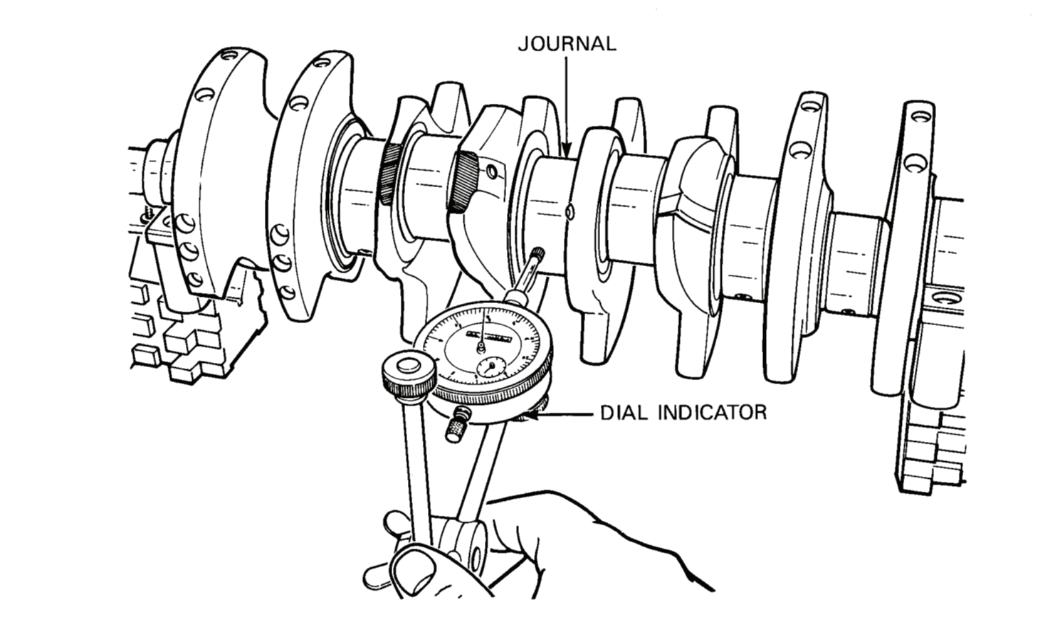
Figure 2-2-9 — Checking Crankshaft Journals for Run-OutClick image to enlarge.
| Repair Stage | Crankshaft Main Journal Diameter | Crankshaft Connecting Rod Journal Diameter |
|---|---|---|
| Original Diameter | 53.978 - 53.958 mm | 45.978 - 45.958 mm |
| Repair Stage 1 | 53.728 - 53.708 mm | 45.728 - 45.708 mm |
| Repair Stage 2 | 53.478 - 53.458 mm | 45.478 - 45.458 mm |
| Repair Stage 3 | 53.228 - 53.208 mm | 45.228 - 45.208 mm |
Figure 2-2-10 — Crankshaft Repair Stage ChartClick image to enlarge.
5.Crankshaft — To check, proceed as follows:
- Using a micrometer, measure the crankshaft main bearing and connecting rod journals. Take measurements at each side of the journal to check for taper, see Figure 2-2-8.
- Check eccentricity. Using a micrometer, take two measurements of the journals, one at 90° from the first, or place the crankshaft on “V” blocks and check run-out with a dial indicator, see Figure 2-2-9.
- Record the measurements of each journal and compare to Figure 2-2-10.
NOTE — If the journals are rough, scored, tapered, or exceed 0.03 mm out of round, the crankshaft must be replaced or reconditioned to the next repair stage.
Intermediate Shaft Bearings
6.Inspection — If the bearings are worn so that the copper backing shows through the silvery bearing surface, drive the bearings out.
Intake Manifold
7.Inspection — To inspect, proceed as follows:
- Using a straight edge, check the mating surfaces of the manifold for distortion. If necessary, surface grind until flat.
- Clean around the ports and ensure the mating surfaces are smooth.
Exhaust Manifold
8.Inspection — To inspect, proceed as follows:
- Inspect the manifold for cracks.
- Using a straight edge, check the mounting surfaces for distortion. If necessary, surface grind until flat.
Flywheel
9.Inspection — To inspect, proceed as follows:
- Inspect the flywheel clutch surface for cracks and burns and replace, if necessary.
- Inspect the ring gear for broken or chipped teeth and replace, if necessary.
Clutch Disc and Pressure Plate

Figure 2-2-11 — Pressure Plate Distortion CheckClick image to enlarge.
10.Inspection — To inspect, proceed as follows:
- Check the contact surface of the pressure plate for signs of heat and cracks.
- Using a straight edge and feeler gauge, inspect the contact surface of the pressure plate for wear and distortion, see Figure 2-2-11. If wear or distortion exceeds 0.30 mm, replace the pressure plate.
- Check the pressure plate cover for cracks and ensure the rivets are tight and undamaged. Replace the pressure plate, if necessary.
- Check the diaphragm spring fingers at the location of the throw-out bearing contact for scoring and grooving. If score marks exceed 0.30 mm in depth, replace the pressure plate.
- Check the friction material of the clutch disc for wear. The minimum allowable distance above the rivet heads is 2.0 mm.
- Check the disc for run-out. Measure 2.50 mm from the outer edge of the disc. The maximum allowable run-out is 0.50 mm.
- Check the disc for loose or broken rivets and replace, if necessary.
Oil Pan Gasket Surfaces

Figure 2-2-12 — Protrusions on Engine BlockClick image to enlarge.
11.Inspection — To inspect, proceed as follows:
- Clean the oil pan gasket surface and the gasket surface on the engine block.
- File smooth all rough areas on the oil pan gasket surface and the gasket surface on the engine block.
NOTE — New replacement engine blocks may have protrusions which will interfere with the proper positioning of the starter motor, see Figure 2-2-12. These protrusions must be ground off before assembling the engine components.
Section 3 — Assembly
Crankshaft Assembly

| 1. | Bearing Cap |
| 2. | Flanged Thrust Bearing |
| 3. | Bearing Shell |
| 4. | Crankshaft |
Figure 2-3-1 — Crankshaft AssemblyClick image to enlarge.
1.Crankshaft — To assemble and install, see Figure 2-3-1 and proceed as follows:
NOTE — Ensure the crankshaft (4), bearing shells (3), bearing caps (1) and saddles are clean and the anti-rotation tabs engage in the notches in the saddles. The centre bearing is a flanged thrust bearing (2). Ensure that the shells with oil holes are placed in the saddles of the engine block.
- Using the original bearings, original-size new bearings, or undersize bearings, depending on the condition of the crankshaft, install the upper bearing shells (with oil holes and lubrication grooves) in the saddles of the engine block.
- Place the crankshaft in the block.
- Place the lower bearing shells in the bearing caps.
- Place a small piece of 0.025 – 0.076 mm Plastigage on each main journal.
NOTE — If checking used bearings or new bearings installed in a high mileage engine, use Plastigage which measures clearances from 0.050 to 0.150 mm.
- Install the bearing caps over the journals. Ensure the #1 cap is at the front and all the numbers are facing away from the intermediate shaft.
- Install the bearing cap bolts and torque to 35 N•m (25 ft lb).
NOTE — Do not turn the crankshaft.

Figure 2-3-2 — Measurement of Crankshaft Bearing ClearanceClick image to enlarge.
- Remove the bolts and bearing caps.
- Using the Plastigage package, measure the bearing clearance as indicated by the squash of the Plastigage, see Figure 2-3-2. The clearance should be 0.03 to 0.08 mm for new bearings. If clearance for used bearings exceeds 0.17 mm, replace the bearings and repeat steps d. through h. If the clearance still exceeds 0.17 mm , replace or recondition the crankshaft.
CAUTION — To prevent damage to the journal, do not scrape off the Plastigage.

Figure 2-3-3 — Measurement of Axial PlayClick image to enlarge.

Figure 2-3-4 — Front Crankshaft Seal CarrierClick image to enlarge.
- Using a cleaning solvent, remove the flattened Plastigage from the journals.
- Remove the crankshaft and coat the upper bearing with assembly lubricant.
- Reinstall the crankshaft and coat the journals with assembly lubricant.
- Coat the bearing caps with lubricant and install them over the journals noting their correct location.
- Install the bolts and torque to 65 N•m (47 ft lb).
- Tap the crankshaft all the way to the rear of the block.
- Insert feeler gauges between the crank throw for No 2 cylinder and the centre main bearing, see Figure 2-3-3. With new parts, axial play should be 0.07 to 0.17 mm. Axial play is excessive if clearance is 0.37 mm or greater. Excessive clearance can usually be corrected by replacing the centre main bearing.
- Remove the old seals from the crankshaft seal carriers and clean the carriers of any gasket material.
- Install new seals in the carriers so that the seal lips will face in when installed.
- Install new gaskets to the carriers and secure the rear carrier to the block with the six cap screws and washers. Torque to 10 N•m (7 ft lb).
- Install a new gasket to the front carrier and secure it to the block with the three cap screws. Torque to 10 N•m (7 ft lb). Do not install cap screws in the top and right centre holes as they are for the timing cover cap screws, see Figure 2-3-4.
Piston Assemblies
2.Piston Pin/Connecting Rod — To assemble and install, proceed as follows:
NOTE — If the pistons or connecting rods are replaced, all four must be of the same weight class. Connecting rod weight classes are designated by a number on the rod cap. Pistons and connecting rods come in sets of four. Unmarked pistons must be within 10 grams of the weight of the other pistons.
- Install one circlip in one end of the piston pin bore.
- Heat the piston in an oil bath to 60°C.
- Insert the connecting rod into the piston so that when the arrow on the piston crown is facing the front end of the engine, the marks on the connecting rod will be towards the intermediate shaft side of the engine.
- Working quickly, so that the piston does not cool, hand press the piston pin into the piston and through the connecting rod bushing. Seat the pin against the circlip that is already installed and then install the second circlip. Ensure the circlips are fully engaged in their grooves.
- Using the ring remover/installer, carefully install the rings in the ring grooves. Install the oil scraper ring first.
NOTE — The top compression ring has a chamfer to the inside top. The second compression ring has a groove to the outside bottom. Both rings must be installed with the word “TOP” towards the piston crown. Install the oil scraper ring and its spring with the lettering towards the piston crown.

Figure 2-3-5 — Position of Ring GapsClick image to enlarge.
- Turn the crankshaft so that No 1 connecting rod journal is at BDC.
- Thoroughly lubricate the cylinder walls and piston rings.
- Stagger the ring gaps so that the oil scraper ring gap is not over the end of the connecting rod pin and the other two gaps offset 120° to each side of the scraper ring gap, see Figure 2-3-5.
- Install the ring compressor over the piston and tighten to fully compress the rings.
- Install the connecting rod upper bearing ensuring that the anti-rotation tab engages in the rod.
- Install the piston/connecting rod assembly in the cylinder, with the arrow on the piston crown facing toward the front of the engine block until the ring compressor contacts the block.
- Using a wooden hammer handle, press the piston into the cylinder until the connecting rod bearing is seated squarely on the crankshaft journal. Ensure that the crankshaft journal is not nicked by the connecting rod studs.
- Install the bearing shell into No 1 cap.
NOTE — If checking used bearings or new bearings installed in a high mileage engine, use Plastigage which measures clearances from 0.050 to 0.150 mm.
CAUTION — Do not lay the Plastigage over the oil hole in the journal.
- Place a piece of 0.025 - 0.076 mm Plastigage on the bearing journal.
- Install the connecting rod cap and torque the nuts to 35 N•m (25 ft lb). Do not turn the crankshaft. Ensure the forged marks or numbers are towards the intermediate shaft.

Figure 2-3-6 — Checking Clearance Between Crankshaft and Connecting Rod BearingClick image to enlarge.

Figure 2-3-7 — Measurement of Connecting Rod Axial PlayClick image to enlarge.
- Remove the cap and measure the bearing clearance with the Plastigage package, see Figure 2-3-6. With new parts, bearing clearance should be 0.028 to 0.088 mm. With used parts, if clearance is at the wear limit, 0.12 mm or greater, install new bearings and recheck the clearance. If the clearance is still excessive, remove the crankshaft and repair it to the next repair stage, see Figure 2-2-10.
- If clearance is within specifications, clean the Plastigage from the journal with solvent, lubricate the bearings and journal.
- Reinstall the cap and torque the nuts to 45 N•m (32 ft lb).
- Install No 4 piston/connecting rod assembly and perform steps p. to u. inclusive.
- Hand turn the crankshaft 180° and install Nos 2 and 3 piston/connecting rod assemblies. Perform steps p. to u. inclusive for each rod assembly.
- Using feeler gauges, check the axial play of each rod by pushing the rod as far as possible to one side and inserting the feeler gauges between the opposite side and the journal, see Figure 2-3-7. Maximum clearance is 0.37 mm. If clearance is in excess, replace the connecting rod or crankshaft.
Oil Pump
3.Installation — Install the pump with two cap screws and flat washers and torque to 20 N•m (15 ft lb).
Oil Pan and Gasket
4.Installation — To install, proceed as follows:
- Install a new gasket on the engine block.
- Install the oil pan.
- Install the twenty cap screws and flat washers. The longest cap screw is installed in the left rear corner and requires a copper washer.
- Torque all cap screws to 10 N•m (7 ft lb).
5.Installation — To install, proceed as follows:
- Ensure the sealing surface, pistons and cylinders are clean and apply engine oil to the cylinder walls.
- Install a new cylinder head gasket on the engine block with the word “OBEN” (TOP) facing up.
- Ensure the sealing surface of the cylinder head is clean and place the head on the engine block.
- Apply an anti-seize compound to the ten cylinder head bolts and washers to prevent seizure to the aluminium head and install the bolts and flat washers.
- Tighten the cylinder head bolts following the sequence shown in Figure 2-1-6 and torque the bolts to 30 N•m (22 ft lb).
- Torque the cylinder head bolts to 58 N•m (43 ft lb) following the sequence described in step e.
- Torque the cylinder head bolts to 75 N•m (55 ft lb) following the sequence described in step e.
- After torquing all cylinder head bolts, turn each bolt a further quarter turn following the sequence described in step e. After completing step h., it will not be necessary to torque the bolts a second time after the engine is hot or broken in.
- Adjust the valve tappet clearance. When cold, the clearance between the intake valves and camshaft lobes should be 0.15 mm to 0.25 mm. When cold, the clearance between the exhaust valves and camshaft lobes should be 0.35 mm to 0.45 mm.
Alternator Bracket (Rear)
6.Installation — Install the alternator rear bracket on the engine block with two cap screws and lock washers and torque to 20 N•m (15 ft lb).
Timing Belt Rear Plate
7.Installation — To install, proceed as follows:
- Install the front alternator bracket and rear plate on the engine block and install the cap screw and washer. Torque the cap screw to 20 N•m (15 ft lb).
- Install the stud that secures the top of the bracket and rear plate to the engine block and torque to 20 N•m (15 ft lb).
- Install the cap screw and washer that secure the timing belt rear plate to the cylinder head and torque the cap screw to 10 N•m (7 ft lb).
Intermediate Shaft and Sprocket
8.Installation — To install, proceed as follows:
- Install new bearings ensuring that the oil hole in the bearing aligns with the oil hole in the block. Use a bearing installer that accurately fits the inside of the bearing.
- Coat the bearings and gear with lubricant or grease and install the shaft.
- With the lip facing in, install a new seal in the seal carrier, install an “0” ring and secure the carrier to the block. Torque the cap screws to 25 N•m (18 ft lb). Check axial clearance. The maximum clearance is 0.25 mm. Replace the seal carrier or the intermediate shaft to correct excessive clearance.
- Install the woodruff key and intermediate shaft sprocket.
- Install the cap screw and flat washer and torque to 80 N•m (59 ft lb).
Crankshaft Sprocket
9.Installation — To install, proceed as follows:
- Install the crankshaft sprocket.
- Install the bolt and flat washer and torque to 80 N•m (59 ft lb).
Timing Belt

Figure 2-3-8 — Camshaft Sprocket Timing MarkClick image to enlarge.

Figure 2-3-9 — Alignment of Intermediate Sprocket and Crankshaft PulleyClick image to enlarge.
10.Installation — To install, proceed as follows:
- Turn the camshaft sprocket until the timing mark on the sprocket is even with the tip at the top of the timing belt rear plate, see Figure 2-3-8. Both camshaft lobes of the #1 cylinder must face up at similar angles.
- Install the crankshaft pulley with the four cap screws and flat washers. Ensure the indentation in the pulley aligns with the protrusion in the sprocket.
- Turn the intermediate sprocket until the punch mark on the sprocket is in line with the “V” mark on the crankshaft pulley, see Figure 2-3-9.
- Place the timing belt on the crankshaft, intermediate and camshaft sprockets. Ensure the sprockets do not turn while the belt is installed. Ensure the teeth of the belt are correctly engaged in the sprockets, and all the slack of the timing belt is on the side nearest the timing belt tensioner.
- Adjust the timing belt tensioner by turning clockwise until the timing belt has the correct tension and then torque the locking nut to 45 N•m (33 ft lb).
NOTE — The timing belt has the correct tension when it can be turned through 90 degrees only, using the thumb and forefinger at a midpoint between the camshaft and intermediate sprockets, or belt deflection is 15 mm.
- Rotate the crankshaft through two complete revolutions. Ensure the timing marks are correctly aligned and recheck timing belt tension.
- Remove the crankshaft pulley.
- Install the lower timing belt cover and torque the cap screws to 10 N•m (7 ft lb).
Coolant Pump
11.Installation — To install, proceed as follows:
- Install a new “O” ring seal in the pump and position the pump on the engine block. Install the four cap screws. The two long cap screws go in the bottom mounting holes. Torque the four cap screws to 20 N•m (15 ft lb).
- Install the two coolant hoses to the pump and tighten the hose clamps.
- Install the bolt, nut and lock washer that secure the lower timing belt cover to the coolant pump and torque to 10 N•m (7 ft lb).
- Install the coolant pump pulley.
Alternator
12.Installation — To install, proceed as follows:
- Install the alternator on the mounting bracket and insert the mounting bolt.
- Install the nut on the mounting bolt.
- Swing down the alternator adjusting arm and loosely install the adjusting bolt and flat washer.
Valve Cover
13.Installation — To install, proceed as follows:
- Ensure the top gasket surface of the cylinder head is clean.
- Place a new rubber half seal on the front camshaft bearing cap.
- Install a new rubber plug at the rear of the cylinder head.
- Install a new cover gasket in the valve cover.

Figure 2-3-10 — Valve Cover Reinforcement BarsClick image to enlarge.
- Install the cover on the head and install reinforcement bars on both sides, ensuring the flat side of the bar faces toward the valve cover and the pointed end points toward the rear of the engine, see Figure 2-3-10.
- Install the timing belt upper cover.
- Place the two spark plug wire retaining brackets and washers on the centre left valve cover securing studs.
- Place the accelerator cable mounting bracket on the second stud from the front on the left side.
- Install a flat washer on both front valve cover securing studs.
- Install the eight nuts and torque to 10 N•m (7 ft lb).
- Install the plug nut in the timing belt upper cover.
Drive Belts
14.Installation — To install, proceed as follows:
- Install the crankshaft pulley. Ensure the indentation on the pulley engages in the protrusion on the crankshaft sprocket and install the cap screws and flat washers. Do not tighten the cap screws at this time.
- Install the drive belts and adjust belt deflection to 15 mm.
- Torque the crankshaft pulley cap screws to 20 N•m (15 ft lb).
- Torque the cap screws for the coolant pump pulley to 20 N•m (15 ft lb).
Oil Filter Housing
15.Installation — To install, proceed as follows:
- Install the oil filter housing and a new gasket with three socket head cap screws and flat washers. Torque the screws to 20 N•m (15 ft lb).
- Coat the gasket of a new oil filter with clean oil and install the filter by hand. Tighten until the gasket contacts the housing and then turn an additional half turn.
- Install the oil temperature sending unit and torque to 10 N•m (7 ft lb).
Distrubitor
16.Installation — To install, proceed as follows:
- Unscrew the three screws from the distributor cap and remove the cap.
- Turn the rotor and shaft until the rotor pickup contact faces toward the TCI electrical connector socket.

Figure 2-3-11 — Oil Pump ShaftClick image to enlarge.
- Turn the oil pump drive lug so that it will align with the slot in the distributor shaft when the distributor is installed, see Figure 2-3-11.
- Ensure that the intermediate sprocket and crankshaft pulley marks are aligned, see Figure 2-3-9. Ensure that the camshaft sprocket timing mark is aligned with the timing belt rear plate, see Figure 2-3-8.
- With the TCI electrical connector facing the rear, insert the distributor shaft into the engine block and then turn the distributor rotor shaft until the gears mesh, the oil pump lug enters the distributor and the distributor sits flush on the block.
- Install the distributor locking collar and cap screw.
- Install the distributor cap.
- Connect the four spark plug high tension cables to the distributor cap in clockwise firing order 1-3-4-2. The spark plug terminal that is nearest the rear of the engine block is the #1 spark plug cable terminal.
Engine Mounting Brackets
17.Installation — To install, proceed as follows:
- Install the right engine mounting bracket with four cap screws and washers and torque to 25 N•m (18 ft lb).
- Install the left engine mounting bracket with three cap screws and washers and torque to 55 N•m (41 ft lb).
Exhaust Manifold
18.Installation — To install, proceed as follows:
- Install the manifold and new exhaust gaskets. Ensure the gaskets are correctly positioned with the inner edge towards the block.
- Install eight nuts and flat washers and torque to 25 N•m (18 ft lb).
Intake Manifold
19.Installation — To install, proceed as follows:
- Install a new gasket on the intake manifold ports and install the manifold.
- Install the socket head cap screws and flat washers and torque to 25 N•m (18 ft lb).
NOTE — The two longer cap screws go in the second hole from either end.
- Install the cap screw that secures the intake manifold to the exhaust manifold bracket and torque to 20 N•m (15 ft lb).
- Torque the nut on the exhaust manifold bracket to 25 N•m (18 ft lb).
- Install the coolant hoses. The lower hose goes to the rear of the cylinder head.
Carburetor
20.Installation — To install, proceed as follows:
- Ensure the carburetor and intake manifold mounting surfaces are smooth and free of nicks and cuts.
- Install the carburetor on the intake manifold, ensuring the side of the carburetor with the air/fuel cutoff valve is nearest the valve cover.
- Install the four cap screws, ensuring the ground wire is attached to the cap screw under the air/fuel cutoff valve.
- Tighten the four cap screws.
- Install the vacuum advance hose.
Intermediate Plate
21.Installation — To install, proceed as follows:
- Remove the engine from the stand.
- Coat the engine side of the intermediate plate with sealing compound and install the plate.
NOTE — Do not apply Loctite to flywheel cap screws if flywheel is to be removed for installation in engine container.
Flywheel
22.Installation — Apply Loctite 270 or 271 to each cap screw. Install the flywheel and cap screws. Torque the cap screws to 75 N•m (55 ft lb).
Crankshaft Pilot Bearing
23.Installation — To install, proceed as follows:
NOTE — To ensure that the pilot bearing seal is correctly positioned, install the bearing with its lettering facing outwards.
- Place a new pilot bearing on the end of the bearing installer tool VW 207C and install the bearing.
- Drive the bearing into the crankshaft and remove the bearing installer tool. The bearing should be 1.5 mm inside the end of the crankshaft.
Clutch Disc and Pressure Plate
24.Installation — To install, proceed as follows:

Figure 2-3-12 — Installation of Clutch AssemblyClick image to enlarge.
- Insert pilot 10-213 into the clutch disc and then into the flywheel.
NOTE — Clutch disc protrusions go towards the pressure plate.
- Install the clutch pressure plate against the flywheel ensuring the indexing pins of the flywheel fit into the indexing holes of the pressure plate, see Figure 2-3-12.
- Install the six socket head screws and torque to 25 N•m (18 ft lb) in a diagonal sequence.
- Withdraw the clutch disc pilot.
Block Heater
25.Installation — To install, proceed as follows:
NOTE — The V-shaped clamping yoke, which retains the block heater to the cylinder block, is spread wider than the frost plug opening when the retaining screw is tightened during installation. If installing a used heater, the yoke must be in good condition and bent to a slightly narrower V-shape than the frost plug opening. Replace the “0” ring if necessary.
- Clean the frost plug opening.
- Apply a light coat of grease to the opening. Do not use gasket sealer.
- Install the block heater, with its element pointing to 6 o'clock, into the right front frost plug opening of the block. Ensure that the heater is fully seated against the block.
- Torque the retaining screw to 190 N•cm (17 in lb).
- Verify that the heater is locked in position by attempting to pull it out of the frost plug opening with pliers.
Cylinder Head Coolant Outlet Connector (LH Side)
26.Installation — Place a new gasket on the connector and install it to the cylinder head using the three cap screws and washers. Torque the cap screws to 10 N•m (7 ft lb).
Cylinder Head Heater Coolant Connector (Rear)
27.Installation — Place a new gasket on the connector and install it to the cylinder head using the two cap screws and washers. Torque the cap screws to 10 N•m (7 ft lb). Install the sending units.
Section 4 — Cylinder Head
Camshaft

Figure 2-4-1 — Camshaft Bearing CapsClick image to enlarge.
1.Removal — To remove, proceed as follows:
- Remove the timing belt tensioner and lock nut.
- Remove the camshaft sprocket cap screw and flat washer.
- Remove the sprocket and woodruff key.
- Remove the nuts and flat washers from camshaft bearing caps one, three and five and set the caps aside, in order, so that each bearing cap will be reinstalled in the same place, see Figure 2-4-1.
- To avoid camshaft distortion, loosen, a little at a time, the four nuts on camshaft bearing caps two and four until the tension is released. Remove the nuts, flat washers and bearing caps, and set the bearing caps aside, in order.
- Remove the camshaft from the cylinder head and remove the seal from the front end of the camshaft.

Figure 2-4-2 — Measurement of Camshaft Run-OutClick image to enlarge.
2.Inspection — To inspect, proceed as follows:
- Inspect the toes and flats of the camshaft lobes for wear and grooving. Wear and grooves are an indication of engine oil contamination.
- Inspect the camshaft bearing surfaces for grooves and replace the camshaft, if necessary.
- Place the camshaft bearing surfaces one and five on V-blocks or inverted bearing caps and, using a dial indicator, measure the run-out of the camshaft, see Figure 2-4-2. Replace the camshaft, if the run-out is greater than .01mm.
- To measure the camshaft axial clearance, proceed as follows:
- Remove the shims and buckettype cam followers from the cylinder head and set aside, in order, so that each will be reinstalled in the same location.
CAUTION — The bearing caps are off centre. If a cap is installed incorrectly, the cap or cylinder head will crack.

Figure 2-4-3 — Measurement of Camshaft Axial ClearanceClick image to enlarge.
- Install the camshaft and bearing caps one and five and install washers and nuts.
- Tap either end of the camshaft so that all the clearance is at one end.
- Place a dial indicator, set at zero, at the end of the camshaft with all the clearance and tap the opposite end of the camshaft, see Figure 2-4-3, to eliminate the clearance at the dial indicator end of the camshaft. If the axial clearance is greater than 0.15 mm, install a new camshaft and measure axial clearance. If the clearance is still unacceptable, replace the cylinder head.
- To measure camshaft bearing clearance, proceed as follows:

Figure 2-4-4 — Measurement of Camshaft Bearing ClearanceClick image to enlarge.
- Install the camshaft and place a small piece of 0.025 - 0.076 mm Plastigage on all five bearing surfaces.
- Install the bearing caps, washers, and nuts in their correct positions and torque to 20 N•m (15 ft lb). Do not turn the camshaft.
- Remove the bearing caps.
- Using the Plastigage package, measure the Plastigage squash, see Figure 2-4-4. The bearing clearance should be 0.02 mm to 0.05 mm. Replace the camshaft if the bearing clearance is greater than 0.05 mm. If the clearance is still unacceptable, replace the cylinder head.
Valves

Figure 2-4-5 — Removal of Valve KeepersClick image to enlarge.

| 1. | Valve Stem |
| 2. | Spring Seat |
| 3. | Stem Seal |
| 4. | Inner Valve Spring |
| 5. | Outer Valve Spring |
| 6. | Valve Spring Retainer |
| 7. | Valve Keepers |
Figure 2-4-6 — Valve AssemblyClick image to enlarge.
3.Removal — To remove, proceed as follows:
- Using either a plastic scraper or solvent, remove the pieces of gasket that are stuck to the cylinder head. Do not use a metal scraper or wire brush.
- Install tool 2036 on the mounting studs of camshaft bearing caps one and five and install four nuts and flat washers, see Figure 2-4-5.
- Using compressor tool VW 541/1, compress the valve springs of each valve assembly and remove both halves of each valve keeper from each valve stem and set aside, in order.
- Remove the valve spring retainer, the inner and outer springs, stem seal and spring seat from each valve stem and set aside, in order, see Figure 2-4-6.
CAUTION — Damage will occur to the valve guides during valve removal if burrs and roughness are not removed first.
- Feel all valve keeper grooves for roughness and, using either a small file, stone, or emery cloth, remove all burrs and roughness before removing the valve from the valve guide in the cylinder head.
- Remove the valves from the valve guides and set aside, in order.

Figure 2-4-7 — Cylinder Head Distortion CheckClick image to enlarge.

Figure 2-4-8 — Measurement of Cylinder Head ThicknessClick image to enlarge.

Figure 2-4-9 — Measurement of Valve Rocking PlayClick image to enlarge.

Figure 2-4-10 — Removal of Valve GuideClick image to enlarge.
4.Cleaning and Inspection — To clean and inspect, proceed as follows:
- Clean the valves with a wire brush.
- Using a straight edge and feeler gauge, check the sealing surface of the cylinder head for distortion, see Figure 2-4-7. If the distortion is greater than 0.10 mm, the head must be resurfaced. After resurfacing, the thickness of the head must not be less than 132.55 mm, see Figure 2-4-8.
- Remove carbon deposits from the valves, valve guides and intake and exhaust ports.
- Using a dial indicator, measure the rocking play at each valve head. Move each valve stem back and forth in its guide and measure the stem movement, see Figure 2-4-9. The stem tip must be flush with the top of the guide. The maximum allowable rocking play of the intake valve stems is 1.00 mm. The maximum allowable rocking play of the exhaust valve stems is 1.30 mm. If the valve exceeds the allowable free play, install a new valve and measure the free play.
- If the new valve exceeds the allowable free play, replace the guide. Proceed as follows:
- From the combustion side of the cylinder head, press out the guide using tool 10-206, see Figure 2-4-10.
CAUTION — To prevent damage to the valve guide seating collars, do not use more than one ton of pressure after the seating collar contacts the cylinder head as the collar may break off.

Figure 2-4-11 — Reaming Valve GuideClick image to enlarge.
- Lubricate the new guide with oil and press into the cold cylinder head from the camshaft side ensuring the shoulder of the guide firmly contacts the top of the cylinder head.
- Ream the valve guide with tool 10-215 to obtain a uniform inside diameter of 8.013 to 8.035 mm, see Figure 2-4-11. Lubricate the reamer with cutting oil while reaming the guide.
- Check the diameter of the guide bore with a go/no-go gauge that has a go diameter of 8.013 mm and a no-go diameter of 8.035 mm. The 8.013 mm end of the gauge should enter the guide easily, but it should be impossible to insert the 8.035 mm end into the valve guide.
- Grind the intake valves, if necessary, to a 45° angle. The intake valves must have a minimum margin of 0.50 mm, see Figure 2-4-12.
CAUTION — Do not grind exhaust valves. Exhaust valves can be lapped only.

Figure 2-4-12 — Specifications for Inlet Valve, Inlet Valve Seats and Exhaust Valve SeatsClick image to enlarge.

Figure 2-4-13 — Valve Spring Compression TestClick image to enlarge.

Figure 2-4-14 — Valve LappingClick image to enlarge.
- Inspect the cylinder head for cracks. Replace the cylinder head if any cracks are noted.
- Inspect the valve seats for burns and pitting and grind to 45 degrees, if necessary. Intake valve seats should have a maximum width of 2.00 mm and exhaust valve seats a maximum width of 2.40 mm, see Figure 2-4-12. Lessen with a 30° stone.
- Using a valve spring tester, test the tension of the springs, see Figure 2-4-13. When the outer springs are compressed to 22.30 mm (7/8 in), the spring pressure should be 43.5 to 48.0 kg (96 to 106 lb). When the inner springs are compressed to 18.30 mm (23/32 in), the spring pressure should be 21.0 to 23.0 kg (46 to 51 lb). Replace valve springs as required.
- Place both halves of each valve keeper in the corresponding keeper groove on each valve stem. Rotate the valve while holding the keepers. The valve stem should rotate freely without excessive free play. If a keeper is loose, grind or file the keeper mating surface to make a tighter fit.
- Set aside all valve keepers in order.
- Lap each valve in its corresponding seat, see Figure 2-4-14.
- Clean all valves, stems and seats.
- Apply a little Prussian blue to each valve at four points where the valve will contact the seat. Insert the valve stems into their corresponding guides and turn each valve one quarter turn in both directions. Withdraw the valves from the cylinder head and examine the circle of bluing on each valve. If the valves are correctly lapped, there will be a complete circle of bluing on each valve. If a circle is incomplete, lap the valve until a complete circle can be formed.
- Clean the bluing from the valves and seats and insert the valve stems into their corresponding guides.
- Place a covering over the bottom of the cylinder head so that the valves will not fall out when the cylinder head is turned over.

Figure 2-4-15 — Installation of Valve Stem SealClick image to enlarge.
5.Installation — To install the valves, proceed as follows:
- Place the spring seats over the corresponding valve stems.
- Place a plastic sleeve from the seal replacement kit on a valve stem to prevent damage when installing valve stem seals.
- Insert the spring end of a seal into valve seal installer tool 10-204, see Figure 2-4-15, and apply a coat of oil to the valve stem.
- Push the seal onto the valve stem and remove the plastic sleeve from the valve stem.
- Install seals on all valve stems following steps b., c. and d. and install the inner and outer springs and retainers on the corresponding valve stems.
- Place bar tool 2036 on the mounting studs of camshaft bearing caps one and five and install four nuts and flat washers.
- Using compressor tool VW 541/1, compress each set of valve springs and place both halves of each valve keeper in the corresponding keeper groove on each valve stem.
- Remove bar tool 2036.
- Tap the top of each valve assembly to ensure the keepers are securely in place.
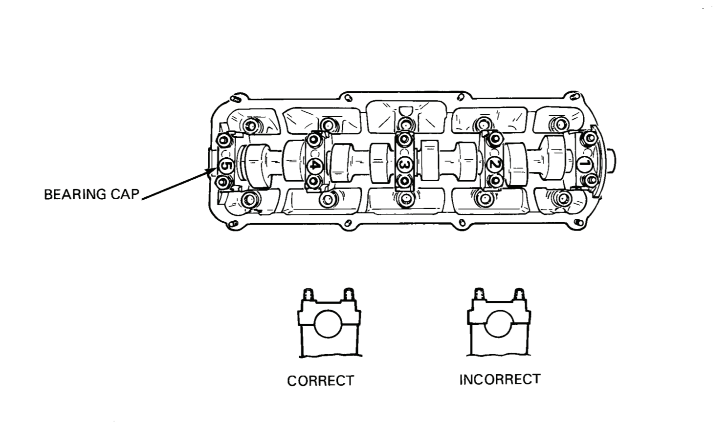
Figure 2-4-16 — Camshaft Bearing CapsClick image to enlarge.
6.Installation — To install the camshaft, proceed as follows:
- Oil the bucket-type cam followers and shims and install on the corresponding valve assemblies.
- Clean and lubricate the camshaft bearing cap surfaces of the cylinder head.
- Ensure all camshaft lubricating holes in the cylinder head are open.
- Lubricate the lip of a new seal and install the seal on the front end of the camshaft with the lip facing toward the rear.
- Install the camshaft.
- Install bearing caps two and four over the corresponding camshaft bearing surfaces, see Figure 2-4-16. Ensure the bearing caps are correctly positioned.
- Install flat washers and nuts on bearing caps two and four and tighten each nut a little at a time. Torque to 20 N•m (15 ft lb).
- Install bearing caps one, three and five over the corresponding camshaft bearing surfaces, ensuring the bearing caps are correctly positioned.
- Install washers and nuts on bearing caps one, three and five and torque to 20 N•m (15 ft lb).
- Install the woodruff key, camshaft sprocket and cap screw. Torque to 80 N•m (59 ft lb).
- Install the timing belt tensioner onto the mounting stud and loosely install the locking nut and flat washer.
- Adjust the valve tappet clearance. When cold, the clearance between the intake valves and camshaft lobes should be 0.15 mm to 0.25 mm. When cold, the clearance between the exhaust valves and camshaft lobes should be 0.35 mm to 0.45 mm.
Section 5 — Torque Values, Special Tools and Specifications
General
1.Figure 2-5-1 lists the torque values for all components used in Part 2.
2.Figure 2-5-2 lists the special tools used in Part 2.
3.Figure 2-5-3 lists the specifications used in Part 2.
| Item No | Item or Component | Torque | |
|---|---|---|---|
| 1. | Crankshaft Bearings | 65 N•m | 47 ft lb |
| 2. | Crankshaft Seal Carrier (front and rear) | 10 N•m | 7 ft lb |
| 3. | Connecting Rod Caps | 45 N•m | 32 ft lb |
| 4. | Oil Pump | 20 N•m | 15 ft lb |
| 5. | Oil Pan | 10 N•m | 7 ft lb |
| 6. | Cylinder Head (refer to Part 2, Section 3) | N•m | ft lb |
| 7. | Alternator Brackets | 20 N•m | 15 ft lb |
| 8. | Timing Belt Rear Plate and Alternator Bracket | 20 N•m | 15 ft lb |
| 9. | Timing Belt Rear Plate (stud) | 20 N•m | 15 ft lb |
| 10. | Timing Belt Rear Plate (at cylinder head) | 10 N•m | 7 ft lb |
| 11. | Intermediate Shaft Seal Carrier | 25 N•m | 18 ft lb |
| 12. | Intermediate Shaft Sprocket | 80 N•m | 59 ft lb |
| 13. | Crankshaft Spocket | 80 N•m | 59 ft lb |
| 14. | Timing Belt Tensioner | 45 N•m | 33 ft lb |
| 15. | Timing Belt Lower Cover | 10 N•m | 7 ft lb |
| 16. | Coolant Pump | 20 N•m | 15 ft lb |
| 17. | Valve Cover | 10 N•m | 7 ft lb |
| 18. | Crankshaft Pulley | 20 N•m | 15 ft lb |
| 19. | Coolant Pump Pulley | 20 N•m | 15 ft lb |
| 20. | Oil Filter Housing | 20 N•m | 15 ft lb |
| 21. | Oil Temperature Sending Unit | 10 N•m | 7 ft lb |
| 22. | Engine Mounting Bracket (right) | 25 N•m | 18 ft lb |
| 23. | Engine Mounting Bracket (left) | 55 N•m | 41 ft lb |
| 24. | Exhaust Manifold | 25 N•m | 18 ft lb |
| 25. | Intake Manifold | 25 N•m | 18 ft lb |
| 26. | Exhaust Manifold Bracket (cap screw) | 20 N•m | 15 ft lb |
| 27. | Exhaust Manifold Bracket (nut) | 25 N•m | 18 ft lb |
| 28. | Flywheel | 75 N•m | 55 ft lb |
| 29. | Clutch Pressure Plate | 25 N•m | 18 ft lb |
| 30. | Camshaft Bearing Caps | 20 N•m | 15 ft lb |
| 31. | Camshaft Sprocket | 80 N•m | 59 ft lb |
| 32. | Block Heater | 190 N•cm | 17 in lb |
| 33. | Cylinder Head Coolant Outlet Connector (LH Side) | 10 N•m | 7 ft lb |
| 34. | Cylinder Head Heater Coolant Connector (Rear) | 10 N•m | 7 ft lb |
Figure 2-5-1 — Engine Torque Values
| Item No | Tool No | Nomenclature | NATO Stock No |
|---|---|---|---|
| 1. | B 183 012 361 | Flywheel holder | 5120-21-899-4887 |
| 2. | VW 207c | Drift | 5120-12-176-4480 |
| 3. | 10-213 | Centering tool | 5120-12-176-1093 |
| 4. | 2036 | Valve mounting device | 5120-21-896-7686 |
| 5. | VW 541/1 | Lever-valve spring | 5120-21-896-7704 |
| 6. | 10-206 | Driver-valve guide | 5120-21-896-7716 |
| 7. | 10-215 | Reamer-valve guide | 5110-21-896-7719 |
| 8. | 10-204 | Driver | 5120-12-181-6870 |
| 9. | 10-202 | Extractor | 5120-12-181-9729 |
Figure 2-5-2 — Special Tools
| Figure | Description | Measurement |
|---|---|---|
| 2-2-1 | Cylinder block distortion | 0.00 - 0.10 mm |
| na | Maximum allowable cylinder block cut to correct distortion | 0.25 mm |
| na | Maximum allowable cylinder bore variation | 0.05 mm |
| na | Maximum allowable cylinder wear | 0.08 mm |
| na | Maximum allowable cylinder wear when fitting new pistons | 0.04 mm |
| na | Original piston diameter | 79.50 mm |
| na | Piston oversizes | + 0.25 + 0.50 + 1.00 mm |
| na | New piston to new cylinder clearance | 0.03 mm |
| 2-2-5 | Maximum allowable piston wear | 0.04 mm |
| 2-2-6 | Piston ring side clearance in piston New parts Wear limit | 0.02 - 0.05 mm 0.15 mm |
| 2-2-7 | Piston ring end gap New compression rings New oil rings Used rings | 0.30 - 0.45 mm 0.25 - 0.40 mm 1.00 mm (Max) |
| na | Piston pin clearance in connecting rod New Wear limit | 0.01 - 0.02 mm 0.04 mm |
| 2-2-8 2-2-9 | Maximum allowable crankshaft journal taper or out-of-round | 0.03 mm |
| 2-3-3 | Crankshaft axial play New Wear limit | 0.07 - 0.17 mm 0.37 mm |
| na | Crankshaft original diameter Main journals Connecting rod journals | 53.978 - 53.958 mm 45.978 - 45.958 mm |
| na | Standard main and connecting rod journal undersizes | – 0.25 – 0.50 – 0.75 mm |
| 2-3-2 | Main bearing clearance New Wear limit | 0.03 - 0.08 mm 0.17 mm |
| 2-3-6 | Connecting rod bearing clearance New Wear limit | 0.028 - 0.088 mm 0.12 mm |
| 2-3-7 | Maximum allowable connecting rod axial play | 0.37 mm |
| 2-4-2 | Maximum allowable camshaft run-out | 0.01 mm |
| na | Maximum allowable camshaft axial play | 0.15 mm |
| na | Camshaft bearing clearance | 0.02 - 0.05 mm |
| na | Intake valve guide stem diameter | 7.97 mm |
| na | Exhaust valve guide stem diameter | 7.95 mm |
| na | Intake and exhaust valve guide bore diameter | 8.013 - 8.035 mm |
| 2-4-9 | Maximum allowable valve rocking play Intake Exhaust | 1.00 mm 1.30 mm |
| 2-4-12 | Maximum allowable valve margin Intake Exhaust | 0.50 mm Do not grind |
| 2-4-12 | Valve face angle Intake Exhaust | 45° Do not grind |
| 2-4-12 | Valve seat angle | 45° |
| 2-4-12 | Valve seat width reduction angle | 30° |
| 2-4-12 | Intake valve seat width | 2.00 mm |
| 2-4-12 | Exhaust valve seat width | 2.40 mm |
| 2-4-13 | Valve spring tension Outer spring Inner spring | 43.5 - 48.0 kg (96 - 106 lb) 21.0 - 23.0 kg (46 - 51 lb) |
| na | Valve clearance-cold Intake Exhaust | 0.15 - 0.25 mm 0.35 - 0.45 mm |
| 2-4-7 | Cylinder head distortion | 0.00 - 0.10 mm |
| 2-4-8 | Minimum allowable cylinder head thickness to correct distortion | 132.55 mm |
| na | Maximum allowable intermediate shaft play | 0.25 mm |
| na | Timing belt deflection | 15 mm |
| 2-2-1 | Maximum allowable pressure plate distortion | 0.30 mm |
| na | Maximum allowable clutch spring finger grooving | 0.30 mm |
| na | Maximum allowable clutch disc run-out | 0.50 mm |
| na | Minimum allowable distance above clutch disc facing rivets | 2.0 mm |
Figure 2-5-2 — Engine Specifications
Part 3 — Transaxle
Section 1 — Disassembly
Transmission

| 1. | Cap |
| 2. | Propeller Shaft Flange |
| 3. | Transmission Cover |
| 4. | Dowel Pin |
| 5. | Short Cap Screws |
| 6. | Transmission Housing |
| 7. | Dowel Pin |
| 8. | Short Cap Screws |
| 9. | Selector Fork Shaft |
| 10. | Spring Pin |
| 11. | Flange Securing Nut |
| 12. | Pinion Shaft |
Figure 3-1-1 — Transmisson AssemblyClick image to enlarge.

Figure 3-1-2 — Removal of Propeller Shaft Drive Flange NutClick image to enlarge.

Figure 3-1-3 — Removal of Propeller Shaft Drive FlangeClick image to enlarge.
1.Removal — To remove, see Figure 3-1-1 and proceed as follows:
- Mount the transaxle on a repair stand.
- Drain the oil.
- Pry the cap (1) from the propeller shaft flange (2).
- Straighten the lock on the flange securing nut (11).
- Remove the flange securing nut using a 36 mm socket and Matra 3028 to hold the flange, see Figure 3-1-2.
- Remove the flange from the pinion shaft (12) using tool VW 391 and a 25 mm open end wrench, see Figure 3-1-3.
- Remove the two dowel pins (4), see Figure 3-1-1, from the transmission. cover (3) and transmission housing (6) (top and bottom).
- Remove the spring pin (10) of the selector fork shaft (9) for cross-country and reverse gears by driving the pin into the case. The pin can be tapped out later when the cover is removed.
- Pull out the shaft (9) for the selector fork.
- Remove the ten long cap screws and two short cap screws (5) securing the cover to the transmission housing.
- Remove the cover from the transmission housing.
- Remove the transmission from the differential housing by removing the two dowel pins (7) and the two securing cap screws (8).
Clutch Release Bearing

| 1. | Securing Springs |
| 2. | Clutch Release Bearing |
| 3. | Cap Screw |
| 4. | Locking Collar |
| 5. | Bushing |
| 6. | Guide Sleeve |
| 7. | Release Shaft |
| 8. | Shaft Stop |
| 9. | Release Shaft Spring |
| 10. | O-ring |
| 11. | Plastic Bushing |
| 12. | O-ring |
| 13. | Platic Cap |
| 14. | Snap Ring |
| 15. | Bolt |
| 16. | Washer |
| 17. | Clutch Lever |
| 18. | Washer |
| 19. | Nut |
Figure 3-1-4 — Clutch Release Bearing and Shaft AssemblyClick image to enlarge.

Figure 3-1-5 — Removal of Clutch Release Shaft BushingClick image to enlarge.
2.Removal — To remove, see Figure 3-1-4 and proceed as follows:
- Remove the left and right clutch release bearing securing springs (1) by using a screwdriver to unhook the springs from the fingers on the shaft (7).
- Pull the release bearing (2) off the guide sleeve (6).
Clutch Release Bearing Shaft and Seals
3.Removal — To remove, see Figure 3-1-4 and proceed as follows:
- Relieve tension on the shaft (7). Using brake spring pliers, grip under the spring and pry the spring (9) to one side using a screwdriver.
- Remove the snap ring (14) and pry off the plastic cap (13).
- Pry the plastic bushing (11) and “O” ring (12) from the shaft.
- Remove the “O” ring from the plastic bushing.
- Work the shaft all the way to one side until it is free of the bushing (5). Push the shaft in the opposite direction until the end is clear of the housing and remove the shaft.
- Using a small screwdriver, pry the “O” ring (10) out of the housing.
- Remove the clutch-shaft stop (8) for access to the bushing.
CAUTION — Ensure the jaws of the extractor do not protrude past the inner edge of the bushing. If the jaws contact the suface of the housing, they will cause damage to the housing.
- Insert internal extractor KUKKO 21/3 and tighten the nut.
- Insert puller VW 771 through the shaft opening in the housing.
- Screw the puller into the bushing puller, using adapter VW 771/15, see Figure 3-1-5.
- Remove the bushing.
Starter Bushing

Figure 3-1-6 — Removal of Starter BushingClick image to enlarge.
4.Removal — To remove, see Figure 3-1-6 and proceed as follows:
- Insert tool 788-14 into the starter bushing.
- Install puller KUKKO 22-1.
- Remove the bushing from the differential housing.
Two-Wheel Drive and Interlock Levers

| 1. | Interlock Lever |
| 2. | Shaft |
| 3. | Spring Pin |
| 4. | Interlock Shaft Cover |
| 5. | Two-Wheel Drive Lever |
| 6. | Shaft |
| 7. | Bolt and Nut |
Figure 3-1-7 — Two-Wheel Drive and Interlock LeverClick image to enlarge.
5.Removal — To remove, see Figure 3-1-7 and proceed as follows:
- Remove the bolt and nut (7) securing the two-wheel drive lever (5) to the shaft (6).
- Mark the lever and the end of the shaft for reassembly.
- Remove the lever.
- Remove the interlock lever (1) from the shaft (2) by driving out the spring pin (3).
- Remove the lever.
- Remove the three socket head cap screws from the interlock shaft cover (4).
- Remove the cover.
Left Drive Flange

Figure 3-1-8 — Removal of Drive Flange Centre BoltClick image to enlarge.

Figure 3-1-9 — Removal of Left Drive Flange SealClick image to enlarge.
6.Removal — To remove, proceed as follows:
- Remove the speedometer driven gear and adapter.
- Install two bolts in the drive flange and hold the bolts with a pry bar.
- Remove the centre bolt from the drive flange, see Figure 3-1-8.
- Pull the drive flange from the housing.
Right Drive Flange
7.Removal — To remove, proceed as follows:
- Pierce and pry out the drive flange cover.
- Install two bolts in the drive flange and hold the bolts with a bar, see Figure 3-1-8.
- Remove the drive flange centre bolt and washer.
- Remove the drive flange.
- Remove the half shaft and needle bearing from the drive flange.
Differential Flange Assembly
8.Removal — To remove, proceed as follows:
- Remove the nine cap screws from the differential flange.
- Remove the differential flange assembly.
- Remove the spacer and shim.
- Remove the crown gear and carrier from the differential housing.
Differential Bearing Races

Figure 3-1-10 — Removal of Pinion Shaft Bearing Race and ShimClick image to enlarge.

Figure 3-1-11 — Removal of Left Carrier Bearing Race and ShimClick image to enlarge.
9.Removal — To remove, proceed as follows:
- Remove the left carrier bearing race and shims using puller KUKKO 21-7, support tool KUKKO 22-2 and a 27 mm wrench, see Figure 3-1-11.

Figure 3-1-12 — Removal of Input Shaft Needle BearingClick image to enlarge.
Input Shaft Needle Bearing
10.Removal — Remove the input shaft needle bearing using extractor KUKKO 21-5 and sliding hammer VW 771, see Figure 3-1-12.
Differential Flange Assembly

| 1. | Oil Seal |
| 2. | Oil Seal |
| 3. | Nut, Bolt and Washers |
| 4. | Two-wheel Drive Lever |
| 5. | Selector Shaft Seal |
| 6. | Snap Ring |
| 7. | Two-wheel Drive Sending Unit |
| 8. | Extension Shaft |
| 9. | Detent Plug |
| 10. | Seal |
| 11. | Spring |
| 12. | Detent |
| 13. | Differential Flange |
| 14. | Selector Shaft |
| 15. | Selector Fork |
| 16. | Snap Ring |
| 17. | Sliding Collar |
| 18. | Bearing Race |
| 19. | Shim |
| 20. | Tubular Key |
| 21. | Magnet |
Figure 3-1-13 — Differential Flange AssemblyClick image to enlarge.
11.Disassembly — To disassemble, see Figure 3-1-13 and proceed as follows:
- Place the differential flange (13) in a vise.
- Pry or drive out the two oil seals (1 and 2).
- Remove the detent plug (9) and seal (10).
- Remove the spring (11) and detent (12).
- Remove the two-wheel drive sending unit (7) and extension shaft (8).
- Remove the seal (5) from the selector shaft (14).
- Remove the snap rings (6 and 16) from the selector shaft.
- Remove the shaft (14), selector fork (15) and sliding collar (17).
- Remove the bearing race (18) and shims (19) from the housing using a brass drift.
- Pull out the tubular key (20) and remove the magnet (21).
Crown Gear and Carrier

| 1. | Shims |
| 2. | Side Gears |
| 3. | Thrust Washers |
| 4. | Pinion Gears |
| 5. | Nuts |
| 6. | Drive Flange Shim(s) |
| 7. | Shaft |
| 8. | Carrier |
| 9. | Tubular Key |
| 10. | Small Carrier Bearing |
| 11. | Speedometer Drive Gear |
| 12. | Cap Screw |
| 13. | Crown Gear |
| 14. | Large Carrier Bearing |
Figure 3-1-14 — Crown Gear and Carrier AssemblyClick image to enlarge.

Figure 3-1-15 — Removal of Large Carrier BearingClick image to enlarge.

Figure 3-1-16 — Removal of Small Carrier BearingClick image to enlarge.

Figure 3-1-17 — Removal of Crown Gear from CarrierClick image to enlarge.
12.Disassembly — To disassemble, see Figure 3-1-14 and proceed as follows:
- Remove the drive flange shim (6).
- Remove the speedometer drive gear (11).
- Secure the assembly in a vise.
- Remove the large carrier bearing (14) using puller KUKKO 44-2 and tool 40-105. Ensure that the puller fits into the grooves on the carrier, see Figure 3-1-15.
- Remove the small carrier bearing (10), see Figure 3-1-14, using puller OTC 1025 and tool 40-105, see Figure 3-1-16.
- Remove the ten cap screws (12), see Figure 3-1-14, from the carrier (8).
- Drive the crown gear off the carrier, see Figure 3-1-17.
- Drive out the tubular key (9), see Figure 3-1-14, that secures the shaft for the pinion gears.
- Drive out the shaft (7) for the pinion gears (4) and side gears (2) and remove the two nuts (5).
- Remove the pinion gears and thrust washers (3) by turning the gears to the opening.
- Remove the side gears and shims (1).
Transmission

| 1. | Shim |
| 2. | Thrust Washer |
| 3. | Reverse Gear |
| 4. | Bushing |
| 5. | Needle Bearing |
| 6. | Hub |
| 7. | Operating Sleeve |
| 8. | Selector Fork |
| 9. | Bushing |
| 10. | Needle Bearing |
| 11. | Cross-Country Gear |
| 12. | Thrust Washer |
| 13. | Pinion Shaft |
Figure 3-1-18 — Reverse and Cross-Country Gear AssemblyClick image to enlarge.
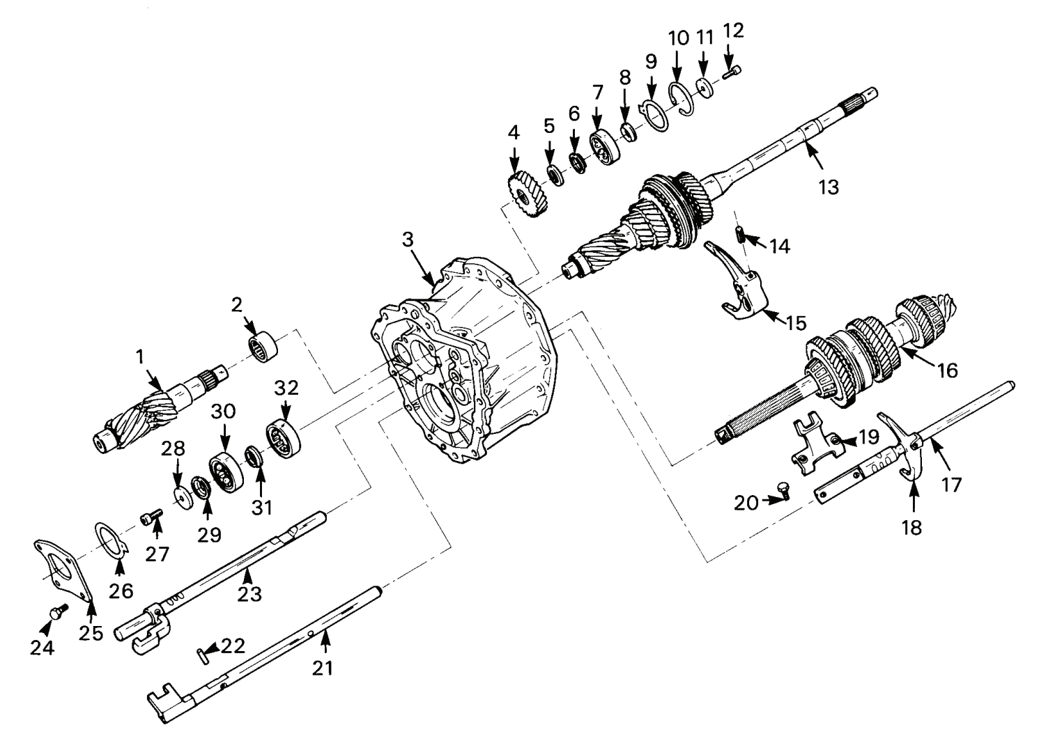
| 1. | Countershaft |
| 2. | Countershaft Needle Bearing |
| 3. | Transmission Housing |
| 4. | Countershaft Reverse Gear |
| 5. | Thrust Washer |
| 6. | Bearing Race |
| 7. | Bearing |
| 8. | Bearing Race |
| 9. | Retaining Washer |
| 10. | Snap Ring |
| 11. | Washer |
| 12. | Socket Head Cap Screw |
| 13. | Input Shaft |
| 14. | Tubular Key |
| 15. | 3-4 Selector Fork |
| 16. | Pinion Shaft |
| 17. | 1-2 Shifter Rod |
| 18. | 1-2 Selector Fork |
| 19. | Operating Link |
| 20. | Cap Screw |
| 21. | 3-4 Shifter Rod |
| 22. | 3-4 Interlock Pin |
| 23. | Cross-Country/Reverse Shifter Rod |
| 24. | Cap Screw |
| 25. | Support Plate |
| 26. | Retaining Washer |
| 27. | Socket Head Cap Screw |
| 28. | Washer |
| 29. | Bearing Race |
| 30. | Ball Bearing |
| 31. | Bearing Race |
| 32. | Roller Bearing |
Figure 3-1-19 — Transmission AssemblyClick image to enlarge.
13.Removal — To remove, see Figure 3-1-18 and proceed as follows:
- Clamp the transmission in a vise.
- Remove the cross-country gear (11) including thrust washer (12), needle bearing (10) and bushing (9).
- Remove the selector fork (8).
NOTE — Mark the operating sleeve (7) and hub (6) for identification (if not removed as a unit).
- Remove the hub with the operating sleeve.
- Remove the needle bearing (5), bushing (4) and reverse gear (3).
- Remove the thrust washer (2) and shim (1). The shim is smaller than the thrust washer.
- See Figure 3-1-19 and remove the socket head cap screw (27) and washer (28) from the input shaft (13) using a 6 mm hex head driver.

Figure 3-1-20 — First and Second Gear Operating LinkClick image to enlarge.
- Remove the operating link for first and second gear by removing the two cap screws and lock washers, see Figure 3-1-20.

Figure 3-1-21 — Gear Dentent Plugs, Plungers and SpringsClick image to enlarge.

Figure 3-1-22 — Cap Screw Installed on Input ShaftClick image to enlarge.
- Remove the gear detent plugs, plungers and springs (green), see Figure 3-1-21.
- Remove the centre gear detent plug using a 6 mm hex head driver, see Figure 3-1-21.
- See Figure 3-1-19 and remove the tubular key (14) from the shifter rod (21) at the selector fork (15) for third and fourth gears.
- Remove the cross-country and reverse gear shifter rod (23) ensuring that the third/fourth shifter rod (21) is in the neutral detent position.
- Remove the interlock pin (22) from the third and fourth gear shifter rod.
- Remove the third and fourth gear shifter rod (21) and selector fork (15) by turning the rod towards the countershaft (1) 90°.
- Remove the four cap screws (24) from the support plate (25) and remove the plate.
- Remove the retaining washer (26).
- Install a support plate M8x20 cap screw fully into the input shaft, see Figure 3-1-22.

Figure 3-1-23 — Support Plate and VW 477h InstalledClick image to enlarge.
- Install the support plate and tool VW 447h with four M8x35 cap screws, see Figure 3-1-23.
- Loosen the cap screw in the centre of the input shaft. This will press the input shaft out of the bearing race (29), see Figure 3-1-19.
- Remove the input shaft (13) and bearing race (31).
- Remove the support plate and ball bearing (30).
- Remove the socket head cap screw (12) and washer (11) from the countershaft (1).

Figure 3-1-24 — Countershaft Snap Ring and Retaining WasherClick image to enlarge.
- Remove the snap ring and retaining washer, see Figure 3-1-24.

Figure 3-1-25 — Removal of CountershaftClick image to enlarge.
- Remove the bearing (7), races (6 and 8) and thrust washer (5), see Figure 3-1-19.
- Remove the countershaft reverse gear (4).
- Remove the pinion shaft (16), shifter rod (17) and attached selector fork (18).
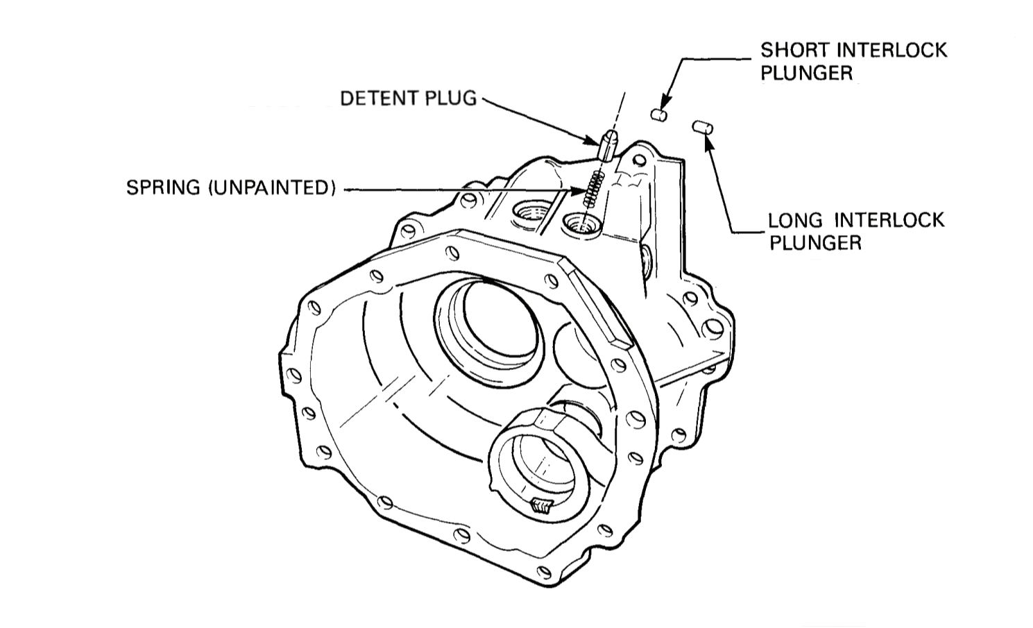
Figure 3-1-26 — Interlocking Plungers, Gear Detent Plug and SpringClick image to enlarge.
- Remove the short and long interlocking plungers and the detent plug and spring (unpainted) from the housing, see Figure 3-1-26.

Figure 3-1-27 — Removal of Countershaft Needle BearingClick image to enlarge.
- Press the countershaft needle bearing out of the transmission housing using tools Matra 30-505 and VW 472/2, see Figure 3-1-27.
- Remove the input shaft roller bearing (32) using a brass drift, see Figure 3-1-19.
- Tap the pinion bearing race and shims out of the transmission housing using remover VW 447i.