
C-30-108-000/MP-001 - First, Second and Third Line Maintenance Instructions — Part 6
C-30-108-000/MP-001 - First, Second and Third Line Maintenance Instructions

1991-06-10 Ch 2695 Pages
PDF (12,573 KB)

C-30-108-000/MP-001
First, Second and Third Line Maintenance Instructions — Part 6
Truck Utility, Light 4 x 4 Military Design Iltis Canadian Series
Issued on Authority of the Chief of the Defence Staff
OPI: DSVPM
1986-10-31
1991-06-10 Ch 2

WARNING — With the exception of the alternator and some minor components (e.g. composite taillight assemblies), all parts on the Iltis Canadian Series are dimensioned in the metric system. During any maintenance procedures, all replacement fasteners must have the same measurement and strength as those removed. (Numbers on the heads of metric bolts and on the surfaces of metric nuts indicate their strength). Mismatched or incorrect fasteners may result in personal injury or engine damage or malfunction. Therefore, fasteners removed from the engine should be saved for re-use in the same location where possible. When fasteners are unsatisfactory for re-use, care should be taken to select a replacement that matches the original.
Part 6 — Body and Chassis Suspension
Section 1 — General Description
General Description
Body
1.The body is a one-piece, all-steel unit that is bolted to the chassis. There are two adjustable front seats and seat belts. Two rear seats can be tipped forward to increase the stowage area in the vehicle. Seat belts are also provided for the rear seats. An aluminium roll bar is provided for the protection of the driver and passengers.
Hood
2.The hood is hinged to the body with two hinge assemblies. It is held open by a hood rod. When closed, the hood is secured to the grille at the front by two flexible hood holddown latches. There is also a safety catch on the right-hand side.
Windshield
3.The windshield consists of a one-piece laminated glass in a metal frame assembly. The windshield is hinged at the bottom and can be lowered to the hood and secured by two straps. It is held in the upright position by two locking levers in the cab, which clamp the lower windshield frame to the body cowling.
Superstructure
4.The superstructure consists of a metal framework which can be disassembled and stored in the vehicle. The doors are removable and can be stored in a stowage bag which can be secured on the hood.
Bumper Assembly
5.A front bumper incorporates a brush guard and two towing hooks. Attached to the bumper are two wire-mesh headlight guards.
Radiator Protection Plate
6.A radiator protection plate fits in front of the radiator grille and protects the radiator when driving through mud or snow or while fording.
Rear Body
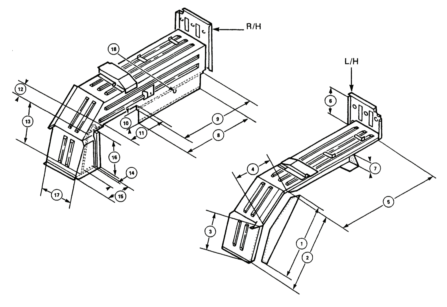
7.On the rear of the body, there are two bumpers, a gas can carrier, a spare wheel bracket, an antenna mounting bracket, a pintle hook, an intervehicular cable receptacle and two A-frame lugs.
Front and Rear Suspension
8.The Iltis is equipped with an independent wheel suspension on control arms with multi-leaf, semi-elliptic, transversal springs and doubleaction shock absorbers.
9.The suspension assembly consists of wishbone arms, leaf spring assemblies and shock absorbers.
- Two wishbone (control) arms are mounted in rubber bushings on the frame at one end and are bolted to the ball joint at the other. They position the lower end of the hub carrier.
- Multi-leaf spring assemblies are mounted across the vehicle for both front and rear suspensions. The assemblies support the vehicle weight and position the upper end of the hub carrier. Each spring assembly is secured to the frame by two U-bolts and to each hub carrier by a trunnion.
- Shock absorbers are bolted to the frame at the top and to the ball joint at the bottom with one of the bolts that secures the wishbone arms to the ball joint. The shock absorbers absorb road shock and overcome spring oscillation. The polyurethane springs on each shock absorber help the leaf spring assemblies to support the vehicle weight under some conditions.
Section 2 — Component Removal and Installation
WARNING — Do not replace metric bolts with standard bolts. See WARNING page at the front of the manual.
Component Removal and Installation
Front Leaf Spring Assembly
1.Removal — It will be necessary to remove several suspension components on the side from which the spring will be withdrawn. To remove, proceed as follows:

Figure 6-2-1 — Front Spring Assembly U-BoltsClick image to enlarge.
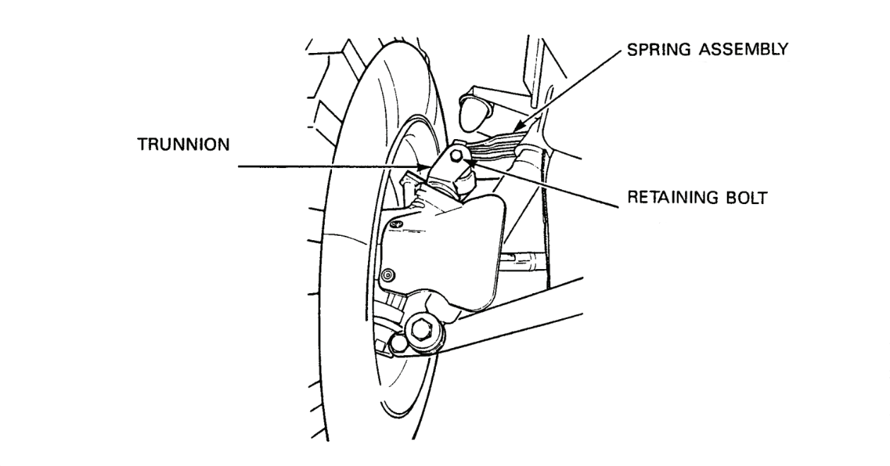
Figure 6-2-2 — Spring Assembly at TrunnionsClick image to enlarge.
- Place the front of the vehicle on axle stands and remove both front wheels.
- Remove the four self-locking nuts from the U-bolts at the centre of the spring assembly, see Figure 6-2-1.
- Remove the retainer plate.
- Support the hub with a jack.
- Remove the bolts from both ends of the spring, see Figure 6-2-2.
- Remove the lower shock absorber bolt.
- Disconnect the flex brake line at the bracket on the steering arm.
- Lower the hub assembly until the end of the spring is free of the trunnion.
- Remove the spring assembly from the housing.
2.Disassembly — To disassemble, proceed as follows:
NOTE — It is not necessary to disassemble the spring assembly if only the bushings are being replaced.

Figure 6-2-3 — Removal of Spring BushingClick image to enlarge.
- Remove the nut and spring centre bolt from the spring assembly. Hold the centre bolt with vise-grips if necessary.
- Separate the four leaves of the springs.
- Remove the four spacers and backing plate (the backing plate is thinner than the spacers).
- Using suitable tools and a hydraulic or bench press, press both bushings from the main leaf, see Figure 6-2-3.
3.Assembly — To assemble, see Figure 6-2-4 and proceed as follows:

Figure 6-2-4 — Installation of Spring BushingClick image to enlarge.
- Clean the inside of both bushing eyes.
- Coat the rubber of both bushings with soap.
- Press a new bushing into each bushing eye.
- Place the backing plate on the main leaf and assemble the leaves in the correct order with a spacer between all leaves and a spacer on top of the fourth leaf.
- Insert the centre bolt from the main leaf to the fourth leaf.
- Install a flat washer and nut on the centre bolt and torque to 47 N•m (35 ft lb).
4.Installation — To install, proceed as follows:
- Insert the spring assembly into the housing.
- Position the retainer plate on top of the assembly and install the two U-bolts and four new self-locking nuts, but do not torque the nuts at this time.
- Install the bolt and new self-locking nut on the side opposite the spring removal. Install the bolt from front to rear.
- Raise the hub carrier and install a spring bolt and a new self-locking nut.
- Install the bolt in the bottom of the front shock absorber, ensuring the bolt is inserted from front to rear. Install a flat washer and a new self-locking nut and torque to 200 N•m (148 ft lb).
- Torque the bolts to 90 N•m (66 ft lb).
- Torque the U-bolt nuts to 175-185 N•m (129-136 ft lb).
- Connect the flex brake line at the steering arm bracket.
- Lower the hub carrier and remove the jack.
Rear Leaf Spring Assembly
5.Removal — Several suspension components must be removed from the suspension on the side from which the spring will be withdrawn. To remove, proceed as follows:
- Fold the rear seats forward.
- Remove the radio sets, if installed.
- Remove the centre floor panel.
- Remove the four machine screws from the U-bolt access plate and remove the plate.
- Remove the spring assembly. Follow the removal procedure for the front leaf spring assembly.
6.Disassembly and Assembly — Follow the disassembly and assembly procedures for the front leaf spring assembly.
7.Installation — To install, proceed as follows:
- Install the spring assembly. Follow the installation procedure for the front leaf spring assembly.
- Install the U-bolt access plate.
- Install the floor centre panel.
- Install the radio sets, if removed.
- Return the rear seats to the upright position.
Shock Absorbers
8.Removal — To remove, proceed as follows:
- Support the vehicle on axle stands and remove the wheel.
- Remove the nut and flat washer from the bottom mounting bolt of the shock absorber.
- Tap the bottom shock absorber mounting bolt free of the shock.
- Remove the top shock absorber mounting bolt.
NOTE — For the rear shock absorbers, slide the top mounting bolt into the recess hole in the vehicle body.
- Remove the shock absorber from the vehicle.
9.Installation — To install, proceed as follows:
- Place the top of the shock absorber in the mount and install the bolt.
- Torque the bolt to 200 N•m (148 ft lb).
- Position the lower end of the shock absorber at the wishbone arm.
- Install the bolt through the wishbone arms and shock absorber.
- Install a flat washer and a new selflocking nut and torque to 200 N•m (148 ft lb).
- Install the wheel and remove the axle stand.
- Torque the wheel bolts to 175 N•m (129 ft lb).
Leaf Spring Bump Stops
10.Removal — Cut off the top of the stop and remove the bump stop from the leaf spring housing.
11.Installation — To install, proceed as follows:
- Apply a light coating of brake fluid or soap solution to the top of the stop.
- Attach a wire to the top of the stop, thread the wire up through the hole in the leaf spring housing and pull the top of the stop through the hole.
- Remove the wire from the stop.
Wishbone Arms
12.Removal — To remove, proceed as follows:
- Place an axle stand under the vehicle frame and remove the wheel.
- Support the weight of the hub on a jack.
- Remove the shock absorber lower bolt, flat washer and nut.
- Remove the nut-and bolt from the wishbone at the frame.
- Remove the nut and bolt from the wishbone arm at the ball joint.
- Remove the wishbone arm.
13.Installation — To install, proceed as follows:
- Install the wishbone arm to the frame, with a bolt and a new self-locking nut and torque to 150 N•m (111 ft lb).
NOTE — Insert bolts from front to rear except for the rear bolt of the right front arm. This bolt is installed from rear to front to avoid interference with the exhaust pipe.
- Install the shock absorber lower bolt through the shock absorber, wishbone arms and the ball joint and secure with flat washer and new self-locking nut. Torque to 200 N•m (148 ft lb).
- Install the bolt through the wishbone arms and the ball joint and secure with a new self-locking nut. Torque to 200 N•m (148 ft lb). On the front assemblies, install the steering stop spacer to the rear of the arm.
- Lower the hub assembly and remove the floor jack.
- Install the wheel, remove the axle stand and torque the wheel mounting bolts to 175 N•m (129 ft lb).
Wishbone Arm Bushings

Figure 6-2-5 — Removal of Wishbone Arm BushingClick image to enlarge.
14.Removal — To remove, proceed as follows:
- Remove the wishbone arm.
- Clamp the arm in a vise and, using a drift and hammer, remove the rubber bushing from each side of the arm, see Figure 6-2-5. It may be necessary to apply penetrating oil to the metal casing that surrounds the bushing and loosen the casing from the arm, using a chisel and hammer.

Figure 6-2-6 — Installation of Wishbone Arm BushingClick image to enlarge.
15.Installation — To install, proceed as follows:
- Using tool 3030, press a new bushing into each side of the arm, see Figure 6-2-6.
- Install the arm.
Front Crossmember
16.Removal — To remove, proceed as follows:
- Remove the engine protection plate.
- Remove the two cap screws from the radiator guard and remove the guard.
- Remove the two cap screws from the crossmember and remove the crossmember.
17.Installation — To install, proceed as follows:
- Install the crossmember with two cap screws.
- Install the radiator guard with two cap screws.
- Install the engine protection plate.
Windshield Wiper Motor
18.Removal — To remove, proceed as follows:
- Check the wiper motor as per the troubleshooting guide (refer to Part 5, Section 3).
- Turn off the battery master switch.
- Remove the plastic cap from the wiper arm at the end of the wiper motor shaft.
- Remove the nut and washer.
- Remove the wiper arm and linkage.
- Remove the cover from the mounting nut.
- Remove the nut from the shaft.
- Remove the washer and rubber grommet.
- Pull the motor away from the windshield frame.
- Remove the two screws and retaining clip from the rubber electrical plug.
- Remove the electrical plug from the motor terminals.
19.Installation — To install, proceed as follows:
- Install the electrical plug into the wiper motor terminals.
- Install the retaining clip and two screws to secure the plug to the motor.
- Insert the motor shaft through the windshield frame until the two indexing pins seat in the corresponding holes in the windshield frame.
- Install the rubber grommet and washer on the shaft.
- Install the nut on the shaft and tighten.
- Install the cover on the nut.
- Install the wiper arm.
- Install the spring washer and nut.
- Install the wiper arm plastic cap.
- Turn on the battery master switch.
- Test for operation.
Windshield Wiper Arms and Linkage
20.Removal — To remove, proceed as follows:
- Remove the plastic cap from the end of each wiper arm post.
- Remove the nut and flat washer from each post and remove both wiper arms and linkage.
21.Installation — To install, proceed as follows:
- Install the wiper arms and linkage on the posts so that the blades are horizontal.
- Install the securing nut and flat washers on the posts.
- If necessary, adjust the wiper arms:
- Loosen the lock nut and adjust the rod so that the wiper arms are in a horizontal position and the blades do not contact the window seal.
- Tighten the lock nut.
- Place a plastic cap on the end of each wiper arm post.
Windshield Frame
22.Removal — To remove, proceed as follows:
- Remove the wiper arms and linkage.
- Remove the wiper motor.
- Remove the rearview mirror.
- Remove the sun visors.
- Remove the three screws from each superstructure securing clamp and remove the clamps.
- Remove the two screws from the windshield securing clamps and remove both clamps.
- Remove the three screws and star washers from the upper half of each windshield hinge.
- Remove the windshield frame.
23.Installation — To install, proceed as follows:
- Position the windshield frame and install the three screws and star washers in the upper half of each windshield hinge.
- Install the windshield clamps on the inside of the windshield frame with two screws.
- Install the two superstructure clamps to the inside upper windshield frame with three screws.
- Install the rearview mirror.
- Install the sun visors.
- Install the wiper motor.
- Install both wiper arms and linkage.
Windshield Glass
24.Removal — To remove, proceed as follows:
- Remove the windshield frame.
- Remove the two machine screws and star washers from each side of the lower front of the frame.
- Remove the lower portion of the frame.
- Slide the windshield glass and rubber seal from the frame.
25.Installation — To install, proceed as follows:
- Install a new seal around the glass if necessary.
- Insert the glass and the seal into the upper portion of the frame.
- Install the lower portion of the frame and secure to the upper portion with two screws and star washers.
- Install the frame.
Rearview Mirror
26.Removal — Grasp the mirror and bracket and turn one-quarter turn counter-clockwise.
27.Installation — Install the mirror bracket into the hole and turn one-quarter turn clockwise. Ensure the bracket is seated securely in the bracket hole.
Front Bumper
28.Removal — To remove, proceed as follows:
- Disconnect the electrical connector from the rear of the blackout drive light housing, remove two cap screws and washers and remove the light and bracket.
- Disconnect the electrical connector from the rear of both blackout marker light assemblies.
- Remove the blackout marker light assemblies from the brackets if the bumper is to be replaced.
- Remove the two rear cap screws and lock washers from the right side of the bumper.
- Support the weight of the bumper, remove the remaining cap screws and lock washers and remove the bumper.
29.Installation — To install, proceed as follows:
- Position the front bumper on the vehicle frame and, while supporting the weight of the bumper, install a lock washer and cap screw on the left and right side of the bumper at the frame.
- Install two cap screws and lock washers on the right side.
- Install the blackout drive light bracket on the left side of the bumper and secure with two lock washers and cap screws.
- Connect the electrical connector into the blackout drive light housing.
- If removed, install the blackout marker lights and connect the electrical connectors.
- Test the operation of the blackout drive light and blackout drive markers.
Radiator Grille
30.Removal — To remove, proceed as follows:
- Remove the two nuts at the top of the grille.
- Remove the four cap screws, flat and lock washers from the grille and lift out the grille.
31.Installation — To install, proceed as follows:
- Slide the radiator grille into place ensuring the lips on the sides of the grille are behind the headlight cover plates.
- Install the grille on the body with four cap screws, flat and lock washers.
- Install the two nuts at the top of the grille on the radiator mounts.
Light Guards
32.Removal — To remove, proceed as follows:
- Remove the two bolts and lock nuts from the side of the light guard.
- Remove the bolt and lock nut from the lower bracket.
- Remove the guard.
33.Installation — To install, proceed as follows:
- Position the guard on the bumper and install the lower bolt and lock nut.
- Install the two bolts and lock nuts on the side.
- Torque all three bolts to 25 N•m (18 ft lb).
Headlight and Park Light Panels
34.Removal — To remove, proceed as follows:
- Remove the three sheet metal screws at the front of the panel and the two screws at the rear of the panel.
- Remove the plastic wiring harness clip from the hole in the fender.
- Disconnect the park light wires.
- Remove the panel and park light assembly from the fender.
- Remove the two screws from the park light lens and remove the lens.
- Squeeze in the two park light locking tabs.
- Remove the park light assembly from the panel.
35.Installation — To install, proceed as follows:
- Install the park light in the panel so that the writing on the back of the light is upside down and snap the retaining clip into place.
- Install the park light lens with the writing upside down and install the two screws.
- Install the light panel to the fender with the three sheet metal screws.
- Connect the electrical wiring.
- Connect the wiring harness clip to the fender.
Pintle Hook
36.Removal — To remove, proceed as follows:
- Remove the four self-locking nuts.
- Remove the pintle hook.
- Remove the four bolts and flat washers.
37.Installation — To install, proceed as follows:
- Install the pintle hook with the lock to the top.
- Install the four bolts, flat washers and self-locking nuts and torque to 60 N•m (44 ft lb).
- Lubricate the pintle hook.
Gas Can Carrier
38.Removal — To remove, proceed as follows:
- Remove the two screws and washers from the licence plate light assembly.
- Remove the two cable clips from the wire harness at the side of the carrier.
- Push the electrical harness through the top centre hole in the carrier and disconnect the licence plate light.
- Pull the wire back through the hole in the carrier.
- Remove the nine cap screws from the carrier and remove the carrier.
39.Installation — To install, proceed as follows:
- Install the carrier with the nine cap screws.
- Feed the electrical wire through the hole in the left corner of the carrier and out through the top centre hole.
- Connect the two bayonnet-type connectors to the licence plate light.
- Install the light assembly on the carrier.
- Install the lens with the plastic protrusion to the right.
- Install two screws and washers.
- Connect the cable to the vehicle body with the three plastic cable clips.
Rear Bumpers
40.Removal — To remove, proceed as follows:
NOTE
- To provide access to the right rear bumper, unhook the tailpipe from the hanger.
- When removing the left front bumper, the licence plate wire must be disconnected from the light.
- Remove the nut from the bolt that secures the composite light wiring harness clamp.
- Remove the two cap screws and star washers from the composite light assembly and ground wire.
NOTE — It is not necessary to fully remove the composite light from the bumper for this procedure. The ground wire must be removed.
- Disconnect the four bayonet-type electrical connectors.
- Remove the clamp from the wires and pull the wires through the bumper.
- Remove the two nuts, bolts and flat washers from the outer side of the bumper.
- Remove the four cap screws from the bottom rear of the bumper.
- Pull the bumper from the vehicle.
- Remove the wiring through the hole to fully release the bumper. Wires are tagged for installation.
41.Installation — To install, proceed as follows:
- Install the bumper with four cap screws and washers in the lower bracket portion. Hand tighten only until the side bolts are installed.
- Install the two side bolts, washers and new lock nuts.
- Tighten the two bolts and the four lower cap screws.
- Feed the wiring through the main hole in the bumper at the vehicle body.
- Connect the wires to the corresponding numbered wires at the composite light assembly.
- Connect the wiring harness clamp with the bolt, lock washer and nut.
- Attach the ground wire to one of the cap screws at the back of the composite light assembly.
- With the two cap screws and star washers, install the light assembly to the bumper.
NOTE
- Hook the tailpipe to the hanger after installing the right rear bumper.
- Connect the licence plate light wire after installing the left rear bumper.
Side Rearview Mirrors
42.Removal — Remove the two screws from the mirror to the side mounting bracket and remove the mirror.
43.Installation — Install the mirror on the mounting bracket with the two screws.
Side Rearview Mirror Mounting Brackets
44.Removal — To remove, proceed as follows:
- Remove the two screws from the mirror at the bracket and remove the mirror.
- Remove the two cap screws and lock washers from the bracket and remove the bracket.
45.Installation — To install, proceed as follows:
- Install the mounting bracket on the cowl beneath the windshield frame with the two cap screws.
- Install the mirror on the mounting bracket with the two screws.
Antenna Bracket
46.Removal — To remove, proceed as follows:
- Remove the five cap screws from the antenna bracket.
NOTE — To remove the right bracket, it is necessary to disconnect the tailpipe from the hanger.
- Remove the four cap screws from the antenna mounting plate and remove the plate.
47.Installation — To install, proceed as follows:
- Install the antenna mounting plate.
- Install the antenna bracket on the vehicle with five cap screws.
- Connect the tailpipe to the hanger, if installing the right bracket.
Accelerator Pedal
48.Removal — To remove, proceed as follows:
- Remove the lock clip from both ends of the pedal shaft.
- Move the pedal and shaft to one side until the shaft is clear of the bracket on the opposite side.
- Repeat step b. at the opposite side until the shaft is clear of the bracket.
- Lift the accelerator cable from the pedal arm.
49.Installation — To install, proceed as follows:
- Install the pedal shaft in both sides of the bracket.
- Install the lock clips on both ends of the pedal shaft.
- Connect the accelerator cable to the pedal arm.
Hand Throttle Stop Bracket
50.Removal — To remove, proceed as follows:
- Remove the throttle cable from the bracket.
- Remove the lock clip from the clevis pin.
- Remove the clevis pin and bracket from the firewall.
51.Installation — To install, proceed as follows:
- Install the bracket with the stop screw to the firewall, using the clevis pin.
- Install the lock clip on the clevis pin.
- Install the throttle cable.
- Adjust the stop screw:
- Apply a load equal to the alternator rated output, to the batteries.
- Pull the throttle fully out.
- Adjust the stop screw until the engine rpm is between 2,700 and 3,300 and apply Loctite #271.
Rifle Clips
52.Removal — Remove the two cap screws and lock washers and pull the clip from the mount.
53.Installation — Place the rifle clip on the mount, install the two cap screws and lock washers and torque to 25 N•m (18 ft lb).
Rifle Blocks
54.Removal — Remove the two cap screws and washers and pull the block from the mount.
55.Installation — Position the rifle block on the mount, install the two cap screws and lock washers and torque to 25 N•m (18 ft lb).
Front Seats

Figure 6-2-7 — Front Seat Centre SupportClick image to enlarge.
56.Removal — To remove, proceed as follows:
- Remove the socket head screw and nut from the first hole in the front of the seat centre support, see Figure 6-2-7.
- Lift up on the adjustment lever and slide the seat toward the rear of the vehicle and out of its tracks.
57.Installation — To install, proceed as follows:
- From the rear, install the seat in the tracks.
- Engage the locking pin in the adjustment handle.
- Lift up on the adjustment lever and slide the seat forward.
- Install the socket head screw and nut in the first hole in the front of the seat centre support.
Rear Seats
58.Removal — To remove, proceed as follows:
- Release the rear seat catch and tilt the seat forward.
- Remove the two cap screws and washers and remove the seat.
59.Installation — To install, proceed as follows:
- Position the rear seat and install the two cap screws and washers.
- Tilt the seat back to the upright position.
Rear Seat Belts
60.Removal — To remove, proceed as follows:
- Tip the rear seats forward and remove the centre floor panel.
- Remove the bolt and lock nut from the centre mounting bracket and remove the seat belt.
- Remove the cap screw from the seat belt end plate at the fender well panel and remove the belt.
61.Installation — To install, proceed as follows:
- Install the seat belt strap on the fender well panel with the cap screw and torque to 55 N•m (41 ft lb).
- Install the seat buckle with the lock on the centre mounting bracket, using the bolt, nut and lock washer and torque to 55 N•m (41 ft lb).
- Install the centre floor panel.
Front Seat Belts
62.Removal — To remove, proceed as follows:
- Lift up on the plastic cap that covers the seat belt bracket on the roll bar to remove the cap.
- Remove the cap screw and flat washer from the bracket and remove the bracket and spacer.
- Remove the cap screw and lock washer from the seat belt reel and remove the strap and reel.
- Remove the cap screw and lock washer from the seat belt buckle and remove the buckle.
63.Installation — To install, proceed as follows:
- Install the seat belt buckle on the inner mount with the cap screw and lock washer and torque to 55 N•m (41 ft lb).
- Position the strap end plate and reel on the outer mount. Ensure the end plate is between the mount and reel. Install the cap screw and lock washer and torque to 55 N•m (41 ft lb).
- Position the seat belt bracket on the roll bar. Install the cap screw and flat washer and torque to 55 N•m (41 ft lb).
- Install the plastic cap on the seat belt bracket.
Roll Bar
CAUTION — The aluminum roll bar must be replaced when damaged. Do not attempt any repairs.
64.Removal — To remove, proceed as follows:
- Remove the tarpaulin and superstructure (refer to the Operator's Manual
C-30-108-000/MB-000). - Remove the seat belts from the roll bar.
- Remove the three cap screws from the bottom of the front roll bar supports.
- Remove the two cap screws from the sides of the front roll bar supports.
- Remove the four cap screws and washers from the rear roll bar supports.
- Lift the roll bar clear of the vehicle.
65.Installation — To install, proceed as follows:
- Position the roll bar on the vehicle with the short roll bar supports to the rear.
- Install the four cap screws and washers on the rear roll bar supports, but do not tighten.
- Install the five cap screws and washers on the front roll bar supports.
- Torque all cap screws to 35 N•m (26 ft lb).
- Install the seat belt brackets with the cap screw, flat washer and spacer on the roll bar.
- Install the two plastic caps.
- Install the superstructure and tarpaulin (refer to the Operator's Manual
C-30-108-000/MB-000).
Footwell Vents
66.Removal — Remove the two screws from each vent and remove the vents.
67.Installation — Install the footwell vents with two screws on each vent.
Defroster Ducts
68.Removal — To remove, proceed as follows:
- Tilt the windshield forward onto the hood.
- Remove the left and right speedometer head covers.
- Remove the speedometer head support bracket from the dash.
- While holding the temperature control cable under the dash, unscrew and remove the temperature control knob.
NOTE — Two screws under the bottom of the footwell vents and two screws above the footwell vents are difficult to see. Push down on the duct to gain access to the two upper screws.
- Remove the eleven screws and washers from the duct.
- Remove the defroster duct.
69.Installation — To install, proceed as follows:
- Position the duct on the dash.
- Install the duct with the eleven screws and washers.
- Screw the temperature control knob onto the temperature control cable.
- Install the speedometer head support bracket.
- Install the speedometer head covers.
- Reposition the windshield.
Speedometer Head
70.Removal — To remove, proceed as follows:
- Check the speedometer as per the troubleshooting guide (refer to Part 5, Section 3).
- Disconnect the battery ground cable.
- Remove the speedometer head covers.
- Loosen the two speedometer head cap screws.
- Turn the speedometer one-quarter turn to release it from the bolts.
- Remove the speedometer head support bracket.
- Unscrew the speedometer drive from the back of the speedometer head.
- Disconnect the electrical wires.
- Remove the speedometer head.
71.Installation — To install, proceed as follows:
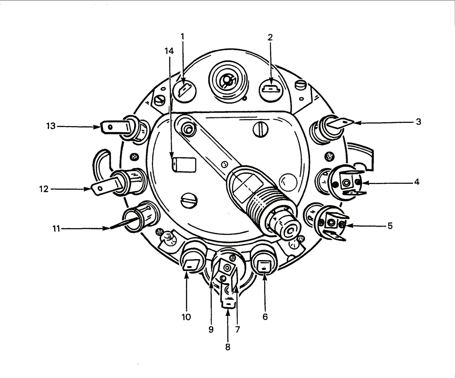
| Item No | Wire No | Circuit |
|---|---|---|
| 1 | 28 | Fuel gauge sending unit. |
| 2 | 27F | Fuel gauge accessory switch. |
| 3 | 40/40A | Speedometer light. |
| 4 | 34/348 and 81F | Oil temperature warning light. |
| 5 | 32/32B and 81E/81F | Coolant temperature warning light. |
| 6 | 34A/18 | Alternator warning light. |
| 7 | 460A | Turn signal indicator light (right turn). |
| 8 | 81D/81E | Alternator light and oil pressure light. |
| 9 | 461A | Turn signal indicator light (left turn). |
| 10 | 35 | Oil pressure warning light. |
| 11 | 4678 | Trailer turn signal indicator light. |
| 12 | 17 | High beam indicator light. |
| 13 | 40A | Speedometer light. |
| 14 | 93E | Ground. |
Figure 6-2-8 — Speedometer Head Electrical TerminalsClick image to enlarge.
- Attach the speedometer drive at the back of the speedometer head.
- Connect the electrical wires to the correct terminals (see Figure 6-2-8).
- Install the speedometer head support bracket.
- Position the speedometer head and tighten the cap screws.
- Install the upper covers.
- Connect the battery ground cable.
Speedometer Cable
72.General — The speedometer cable, a flexible drive inside a flexible housing, is connected to the speedometer drive gear on the front differential and to the speedometer head. If the speedometer fails to operate, disconnect the speedometer cable from the speedometer head, inspect the drive tip and ensure the speedometer head is not seized. If the drive and head are not faulty, replace the speedometer cable.
73.Removal — To remove, proceed as follows:
- Remove the speedometer covers.
- Loosen the two speedometer head cap screws and remove the speedometer head.
- Remove the speedometer head support bracket.
- Unscrew the cable from the speedometer head.
- Pull the outer grommet through the hole in the firewall to the engine side.
- On the dash side, coat the inner grommet with tire soap and force the grommet through the firewall.
- Pull the speedometer cable through the firewall.
- Disconnect the other end of the speedometer cable from the front differential housing.
NOTE — Ensure the grommet remains on the small diameter of the cable.
74.Installation — To install, proceed as follows:
- Insert the speedometer drive end of the cable through the opening in the firewall, from the engine side.
- Coat the inner grommet with tire soap and force it through the opening in the firewall.
- Insert the drive cable into the speedometer head. Ensure that the square sides of the drive tip are aligned with the square sides of the speedometer head. If necessary, turn the cable slightly. Tighten the speedometer cable finger tight.
- Ensure all electrical connections to the speedometer head are properly connected.
- Force the outer grommet through the opening in the firewall until the inner lips protrude through the firewall.
- Push the inner grommet into the outer grommet.
- Install the speedometer head support bracket.
- Engage the speedometer head on the two cap screws in the bracket and tighten the screws.
- Install the speedometer head covers.
- Insert the differential drive end of the speedometer cable into the differential housing. Ensure the square sides of the drive cable align with the square sides of the differential speedometer drive.
- Secure the speedometer cable to the differential housing with the speedometer coupling.
Sun Visors
75.Removal — To remove, proceed as follows:
- Remove the two screws and star washers from the sun visor brackets on the windshield frame and remove the brackets and sun visors.
- Remove the brackets from the visor arms.
76.Installation — To install, proceed as follows:
- Install two sun visor brackets on the visor arms.
- Install the visor brackets on the windshield frame with two screws and star washers, ensuring the visor brackets engage in the brackets on the windshield.
Floor Panels
77.Removal — To remove, proceed as follows:
- Tilt the rear seats forward.
- Remove the eight cap screws, flat and lock washers at the rear of the panels.
- Remove the screw at the rear of each side panel.
- Remove the eight screws from the front of the panels and remove the five panels.
78.Installation — To install, proceed as follows:
- Install the two side panels with the cutaway portions of the panels at the front and next to the fender well.
- Install the widest centre floor panel with the cutaway portion of the panel towards the front and insert the seat belt buckles through the hole in the panel.
- Install the remaining two panels with the cutaway portions of the panels towards the front and over the seat retaining brackets.
- Install the eight screws at the front of the panels.
- Install a screw at the rear of each side panel.
- Install the eight cap screws, flat and lock washers at the rear end of the panels.
- Tilt the rear seats back into position.
Floor Panel Rails
79.Removal — To remove, proceed as follows:
- Remove the floor panels.
- Remove the 32 cap screws, lock and flat washers from the rails and remove the rails and eight rubber spacer pads.

Figure 6-2-9 — Floor Panel Rails and Spacer PadsClick image to enlarge.
80.Installation — To install, see Figure 6-2-9 and proceed as follows:
- Place four spacer pads at the rear mounting holes and four spacer pads on the middle of the rails between the rails and the gas tank cover plate.
- Place the rails on the spacer pads, ensuring the cutaway portions of the side rails are at the front and nearest the fender well.
- Install the eight long cap screws, flat and lock washers in the rail holes above the spacer pads.
- Install the remaining cap screws, flat and lock washers, saving eight long cap screws for the rear of the rails.
NOTE — The remaining eight long cap screws also secure the floor panels at the rear.
- Install the floor panels.
Hood
81.Removal — To remove, proceed as follows:
- Raise the hood and disconnect the windshield washer hose from the nozzle and two clips.
- Lower the hood and remove the six machine screws and star washers from the two hinges that secure the hood to the vehicle.
- Release the hood safety catch.
- Lift the hood from the vehicle.
82.Disassembly — To disassemble, proceed as follows:
- Remove the screws from the six door stowage cleats.
- Remove the four cap screws from the hood securing catches.
- Remove the four rivets from the two windshield securing straps and remove the straps.
- Remove the clip and pin from the hood safety catch.
- Remove the spring and catch.
- Loosen the two nuts from the striker pins.
- Remove the two striker pins.
- Remove the two plastic clips from the windshield washer hose clips.
- Remove the windshield washer nozzle by squeezing the spring clip and pulling the nozzle through the hole.
- Remove all grommets.
83.Assembly — To assemble, proceed as follows:
- Install all grommets.
- Install the windshield washer nozzle by squeezing the spring clip and inserting the nozzle through the hole. Ensure the spray holes in the nozzle face the windshield.
- Install the windshield washer hose plastic clips.
- Install the two striker pins into the holes in the front of the hood.
- Tighten the two nuts on the striker pins.
- Install the spring and the hood safety catch with the clip and pin.
- Install the two windshield securing straps on the hood with four new rivets.
- Install the hood securing catches with the four cap screws.
- Install the six door stowage cleats with screws.
84.Installation — To install, proceed as follows:
- Position the hood on the vehicle.
- Install the hinges with the six machine screws.
- Feed the windshield washer hose through the two clips and connect it to the nozzle.
- Adjust the windshield washer spray nozzle.
Windshield Washer Reservoir
85.Removal — Disconnect the washer line from the outlet on the reservoir cap and lift the reservoir from its bracket.
86.Installation — Place the reservoir on its bracket and connect the washer line to the outlet on the reservoir cap. Ensure the end of the hose is near the bottom of the reservoir.
Windshield Washer Pump
87.Removal — To remove, proceed as follows:
- Check the pump as per the troubleshooting guide (refer to Part 5, Section 3).
- Turn off the battery master switch.
- Remove the washer hoses from the pump.
- Disconnect the electrical wires from the terminals on the side of the pump.
- Remove the two mounting screws from the pump bracket and remove the pump.
88.Installation — To install, proceed as follows:
- Install the pump and bracket with two cap screws.
- Connect electrical wire
#51to the front terminal and wire #91K to the rear terminal. - Connect the washer hose from the reservoir to the front of the pump.
- Connect the washer hose from the nozzle to the rear of the pump.
- Turn on the battery master switch.
- Test the pump.
Spring Housings
89.Removal — To remove, proceed as follows:
- Remove the body from the frame.
- Remove all suspension and power train components.
CAUTION — The frame is a sealed unit. Do not cut or puncture the frame when removing the spring housing.
- Using a high speed grinder with cutoff disc, cut the spring housing from the frame and remove the housing. Cut the spring housing ahead of the weld and discard.
90.Installation — To install, proceed as follows:
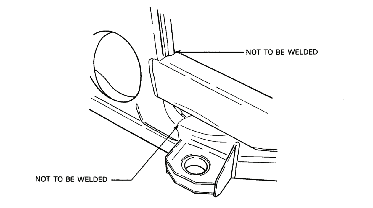
Figure 6-2-10 — Areas of Spring Housing Not To Be WeldedClick image to enlarge.
- A frame jig is recommended to ensure correct alignment of the spring housing to the frame. MIG weld using a filler wire meeting CSA W48.4 class ER 480S-6 specifications. See Figure 6-2-10 for the location of those areas that are not welded. Thoroughly clean the welded area. Apply SAHM-CHEMIE #VP-8919 PVC sealant. Prime and paint (refer to section 3).
- Install the body on the frame.
Body Assembly
91.Removal — To remove, proceed as follows:
- Remove the following components from the inside of the vehicle:
- Tarpaulin, doors and superstructure;
- Batteries;
- Front seats and rear seats;
- Front and rear seat belts;
- Rifle clips and blocks;
- Radio power supply box (refer to Part 5, Section 2);
- Fire extinguisher and bracket;
- Hand brake lever (refer to Part 4, Section 2);
- Rear differential lock lever and two-wheel drive lever;
- Transmission shift lever and tower (refer to Part 3, Section 1);
- Steering column assembly (refer to Part 4, Section 1);
- Accelerator pedal;
- Windshield assembly and windshield locking levers;
- Speedometer head;
- Defroster ducts and footwell vents;
- Gauge panel and warning lights (refer to Part 5, Section 2);
- Hazard and heater fan switches (refer to Part 5, Section 2);
- Throttle and choke controls;
- Heater assembly and temperature control (refer to Part 2, Section 3);
- Map reading light;
- Switch panel and circuit breaker board;
- Battery master switch (refer to Part 5, Section 2);
- Slave receptacle (refer to Part 5, Section 2);
- Turn/brake signal unit;
- Roll bar assembly;
- Rear floor panels and rails;
- All wiring harnesses inside the vehicle.
- Remove the following components from the outside of the vehicle:
- Both side rearview mirror brackets;
- Spare wheel and trailer adapter;
- Rear bumpers;
- Both composite tail-light assemblies;
- Gas can carrier;
- Antenna brackets;
- Gas tank filler neck (refer to Part 2, Section 1);
- Front bumper;
- Hood;
- Engine protection plate;
- Radiator guard;
- Radiator grille;
- Radiator support with radiator and fan assembly (refer to Part 2, Section 3);
- Front crossmember;
- Headlight and park light panels;
- Tarpaulin holddown cord knobs;
- Tarpaulin rear flap hooks.
- Remove the following components from the engine compartment:
- Horn (refer to Part 5, Section 2);
- Coolant expansion reservoir (refer to Part 2, Section 3);
- Ignition coil and suppressor (refer to Part 2, Section 5);
- Windshield washer reservoir;
- Windshield washer pump;
- Brake servo (refer to Part 4, Section 2);
- Clutch cable (refer to Part 3, Section 1);
- Choke cable (refer to Part 2, Section 1);
- Accelerator cable (refer to Part 2, Section 1);
- TCI unit (refer to Part 5, Section 2);
- Ballast resistors (refer to Part 2, Section 5);
- Air intake duct (refer to Part 2, Section 2);
- Air cleaner assembly (refer to Part 2, Section 2);
- Transaxle breather hose;
- Transaxle vent hose;
- Left and right wiring harnesses;
- Fuel by-pass reservoir (refer to Part 2, Section 1);
- Fuel lines;
- Vehicle ground cable from fender;
- Hood support rod;
- Block heater cord.
- Remove the following components from the underside of the vehicle:
- Hand brake cables (refer to Part 4, Section 2);
- Two-wheel drive linkage;
- Rear differential lock linkage;
- Steering rack assembly (refer to Part 4, Section 1);
- All body securing bolts.
- Remove the exhaust system from the rubber hangers.
- Lift the body from the frame.
92.Installation — To install, proceed as follows:
- Position the body on the frame.
- Place the exhaust system on the rubber hangers.
- Install the following components on the underside of the vehicle:
- All body securing bolts and torque to 45 N•m (33 ft lb);
- Steering rack assembly (refer to Part 4, Section 1);
- Two-wheel drive linkage;
- Rear differential lock linkage;
- Hand brake cables (refer to Part 4, Section 2).
- Install the following components in the engine compartment:
- Block heater cord;
- Hood support rod;
- Vehicle ground cable;
- Fuel lines;
- Fuel by-pass reservoir (refer to Part 2, Section 1);
- Left and right wiring harnesses;
- Transaxle vent hose;
- Transaxle breather hose;
- Air cleaner assembly (refer to Part 2, Section 2);
- Air intake duct (refer to Part 2, Section 2);
- Ballast resistors (refer to Part 2, Section 5):
- TCI unit (refer to Part 2, Section 5);
- Clutch cable (refer to Part 3, Section 1);
- Choke cable (refer to Part 2, Section 1);
- Accelerator cable (refer to Part 2, Section 1);
- Brake servo (refer to Part 4, Section 2);
- Windshield washer pump;
- Windshield washer reservoir;
- Coil and suppressor (refer to Part 2, Section 5);
- Coolant expansion reservoir (refer to Part 2, Section 3);
- Horn (refer to Part 5, Section 2).
- Install the following components on the outside of the vehicle:
- Tarpaulin rear flap hooks;
- Tarpaulin holddown cord knobs;
- Headlight and park light assemblies and connect the wiring harnesses to the assemblies;
- Front crossmember;
- Radiator support with radiator and fans (refer to Part 2, Section 3);
- Radiator guard;
- Radiator grille;
- Hood;
- Engine protection plate;
- Front bumper;
- Gas tank filler neck (refer to Part 2, Section 1);
- Antenna brackets;
- Gas can carrier;
- Both rear bumpers;
- Both composite tail-light assemblies;
- Spare wheel and trailer adapter;
- Both side rearview mirror brackets;
- Install the following components inside the vehicle:
- All wiring harnesses;
- Floor panel rails and rear floor panels;
- Circuit breaker board;
- Roll bar assembly;
- Turn/brake signal unit;
- Slave receptacle (refer to Part 5, Section 2);
- Battery master switch (refer to Part 5, Section 2);
- Switch panel;
- Map reading light;
- Heater assembly and temperature control (refer to Part 2, Section 3);
- Throttle and choke controls;
- Hazard and heater fan switches (refer to Part 5, Section 2);
- Gauge panel and warning lights (refer to Part 5, Section 2);
- Defroster ducts and footwell vents;
- Speedometer head assembly;
- Windshield assembly and locking levers;
- Accelerator pedal;
- Steering column assembly (refer to Part 4, Section 1);
- Transmission shift lever and tower (refer to Part 3, Section 1);
- Rear differential lock lever and two-wheel drive lever;
- Hand brake lever (refer to Part 4, Section 2);
- Fire extinguisher and bracket;
- Front seat belts and rear seat belts;
- Radio power supply box (refer to Part 5, Section 2);
- Rifle clips and blocks;
- Front seats and rear seats;
- Batteries;
- Superstructure, tarpaulin and doors.
Body Mounting Bolts (Rear)

Figure 6-2-11 — Location of Rear Body Mounting BoltsClick image to enlarge.
93.Removal — The heads of the two rear body mounting bolts are welded to the body. To remove these bolts, see Figure 6-2-11 and proceed as follows:
- Remove the centre and two intermediate floor panels.
- Remove the two centre rails.
- Remove the spring U-bolt access plate and seal.
- Draw lines #1 and #2 through the centre of the bolt holes.
- Draw lines #3 and #4 at the mid-point of the bolt holes.
- Measure 71 mm from line #1 along lines 3 and 4, towards the rear of the vehicle, and scribe centre marks. The centre of the bolt heads is directly under the centre marks.
- Centre punch both locations.
- Using a 35 mm hole saw, drill through the body to the mounting bolt.
- Centre punch the head of the bolt.
CAUTION — Do not drill or cut into the body channel.
- Drill through the head with a 6 mm drill bit and then a 10 mm bit.
- Remove as much as possible of the head with a 30 mm drill bit.
- Carefully remove the remainder of the bolt head with a chisel.
94.Installation — To install, proceed as follows:
- Install two new M10 x 30 body mounting bolts and two washers on each bolt.
- Install a washer and new self-locking nut on each bolt and torque to 45 N•m (33 ft lb).
- MIG weld using a filler wire meeting CSA W48.4 class ER 480S-6 specifications. Ensure the rubber mounts are not burned.
- Thoroughly clean the welded area. Prime and paint (refer to Section 3).
- Apply a bead of RTV sealant around the 35 mm holes.
- Install the floor rails and floor panels.
Frame Assembly
95.Removal — To remove, proceed as follows:
- Support the vehicle frame on four axle stands and remove the wheels.
- Disconnect and remove the batteries.
- Remove the power pack (refer to Part 2, Section 7).
- Remove the exhaust system (refer to Part 2, Section 2).
- Disconnect and remove all gas and brake lines from the frame.
- Disconnect and remove all electrical wiring from the frame.
- Disconnect and remove the hand brake cables (refer to Part 4, Section 2).
- Remove the two-wheel drive linkage.
- Remove the rear differential lock linkage.
- Remove the brake lines from the spring housings.
- Remove the upper shock absorber bolt from each of the four shock absorbers.
- Disconnect the front tie-rod ends from the steering arms.
- Remove all eight body securing bolts.
- Remove the gas tank filler neck (refer to Part 2, Section 1).
- Lift the vehicle body from the frame.
- Remove the four drive axles (refer to Part 3, Section 4) and propeller shaft (refer to Part 3, Section 2).
- Remove the rear differential (refer to Part 3, Section 3).
- Remove the gas tank and fuel pump (refer to Part 2, Section 1).
- Remove the rear tie-rods.
- Remove the front and rear spring assemblies from the spring housing.
- Remove the wishbone arms from the mounts at the frame.
Frame Mounts and Brackets
96.All frame mounts and brackets are welded to the frame except for the front crossmember mount, which is bolted.
97.Removal — To remove, proceed as follows:
- Unbolt the front crossmember mount.
CAUTION — The frame is a sealed unit. When removing mounts and brackets that are welded to the frame, do not cut or puncture the frame.
- Using a high speed grinder with cutoff disc, remove the frame mounts and brackets that are welded to the frame.
98.Installation — Bolt new front crossmember mounts onto the frame. A frame jig is recommended to ensure correct alignment of parts during welding to the frame. MIG weld all parts using a filler wire meeting CSA W48.4 class ER 480S-6 specifications. Thoroughly clean the welded area. Prime and paint (refer to Section 3). To install the frame assembly, proceed as follows:
- Support the frame on four axle stands.
- Install the wishbone arms to the mounts on the frame and torque the bolts to 150 N•m (111 ft lb).
- Install the front and rear spring assemblies.
- Connect the rear tie rods to the rear spring housing and torque to 60 N•m (44 ft lb).
- Connect the rear tie-rod ends to the steering arms and torque to 40 N•m (30 ft lb).
- Install the fuel pump and gas tank (refer to Part 2, Section 1).
- Install the rear differential (refer to Part 3, Section 3).
- Install the four drive axles (refer to Part 3, Section 4) and propeller shaft (refer to Part 3, Section 2).
- Position the body on the frame.
- Install the eight body securing bolts and torque to 45 N•m (33 ft lb).
- Install the gas tank filler neck (refer to Part 2, Section 1).
- Connect the front tie-rod ends to the steering arms.
- Install the four shock absorbers and torque the upper shock absorber bolts to 200 N•m (148 ft lb).
- Install the brake lines on the spring housings.
- Install the two-wheel drive linkage.
- Install the rear differential lock linkage.
- Install the hand brake cables (refer to Part 4, Section 2).
- Install all gas and brake lines on the frame.
- Install all electrical wiring on the vehicle frame.
- Install the exhaust system (refer to Part 2, Section 2).
- Install the power pack (refer to Part 2, Section 7).
- Install the wheels.
- Install and connect the batteries.
- Remove the axle stands.
- Torque the wheel bolts to 175 N•m (129 ft lb).
Replacement of Body Panels
WARNING — Panel removal and installation procedures must be adhered to. Parting cuts must be made as specified because the separation and subsequent joining affect the rigidity of the body, vehicle road worthiness and safety.

| Item No | Body Panel |
|---|---|
| 1 | Cowl panel |
| 2 | Rear panel crossmember |
| 3 | Rear panel |
| 4 | Rear wheel-well |
| 5 | Rear side panel |
| 6 | Outer side panel |
| 7 | Front side panel |
| 8 | Front wheel-well |
| 9 | Headlight mountings |
Figure 6-2-12 — Location of Body PanelsClick image to enlarge.
99.General — The body and floor panels are predominantly made from cold-worked, deepdrawn sheets. Damage should be straightened without the application of heat, using a body straightening unit. See Figure 6-3-1 for body dimensions. Straighten adjacent areas before removing a damaged panel. Ensure that all welds which separate during the straightening operation, are repaired. Panels are received primed and painted. See Figure 6-2-12 for identification of panels. Areas requiring welding must be ground. MIG welding must be done with a filler wire meeting CSA W48.4 class ER-480S-6 specifications. Spot welds and plug welds are to be evenly spaced. For information on sealing, undercoating, priming and painting of repaired areas, refer to Section 3.
Front Side Panels

| Area No | Minumim Quantity | Length (mm) - Pitch (mm) | |
|---|---|---|---|
| Spot Welds | Plug Welds | Mig Welds | |
| 1 | 12 | ||
| 2 | 29 | ||
| 3 | 5 | Continuous | |
| 4 | 6 | ||
| 5 | 2 | ||
| 6 | 3 | ||
| 7 | 2 | ||
| 8 | 8 | ||
Figure 6-2-13 — Front Side Panel (LH Side)Click image to enlarge.
100.Removal — To remove see Figure 6-2-13 and proceed as follows:
- Using a pneumatic chisel or a spot weld drill, chisel welds at areas 1, 2 and 4 through 8.
- Using a pneumatic cutter, make a parting cut at area 3 that is 20 to 30 mm ahead of the existing spot-welded edge.
- Using a disc grinder, separate the panel from the wheel-well at area 5.
- Using a pneumatic grinder and pliers, remove remnants from areas of the wheel-well that correspond to areas 1, 2 and 4 through 8 of the panel.
- Using off-set pliers, off-set area 3 of the panel.
101.Installation — To install, see Figure 6-2-13 and proceed as follows:
- Using an angle grinder, grind areas 1 through 8 of the new panel.
- Place a new panel on the damaged area and cut to the correct length, allowing for an overlap in area 3.
- Position the new panel on the vehicle and clamp into place at all eight areas.
- Using a spot-welder, spot weld a single row at areas 1 through 8.
- Using MIG welding, weld a continuous weld at area 3. Perform this weld in stages and allow the weld to cool after each stage to reduce heat distortion.
- Using a disc grinder, grind all externally visible welds.
- Fill all externally visible welds with body-filler and sand in preparation for primer.
- Clean all remaining welds with a wire brush and sand in preparation for primer.
- Prime all repaired areas (refer to Section 3).
- Using PVC sealant (refer to Section 3), seal areas 1 through 8.
- Renew underbody PVC sealant (refer to Section 3), in the repaired areas.
- Paint the repaired areas (refer to Section 3).
- Apply bituminous preservative to cavities in the repaired area (refer to Section 3).
Front Wheel-wells

| Area No | Minumim Quantity | Length (mm) - Pitch (mm) | |
|---|---|---|---|
| Spot Welds | Plug Welds | Mig Welds | |
| 1 | 5 | Continuous | |
| 2 | 10 | ||
| 3 | 4 | ||
| 4 | 8 | ||
Figure 6-2-14 — Front Wheel Well (LH Side) CageClick image to enlarge.
102.Removal — To remove, see Figure 6-2-14 and proceed as follows:
CAUTION — When removing welds in area 4, do not damage the reinforcing plate near the lower part of area 4.
- Using a pneumatic chisel or spot weld drill, remove welds at areas 2, 3, and 4.
- Using a pneumatic cutter, make a parting cut at area 1 that is 20 to 30 mm ahead of the existing spot-welded edge.
- Using a pneumatic grinder and pliers, remove remnants from areas of the vehicle that correspond to areas 2, 3 and 4 of the panel.
- Using off-set pliers, off-set the area of the vehicle that corresponds to area 1 of the panel.
103.Installation — To install, see Figure 6-2-14 and proceed as follows:
- Using an pneumatic grinder, grind areas 1 through 4 on the new panel.
- Place a new panel on the damaged area and cut to the correct length, allowing for an overlap in area 1.
- Drill or punch holes for plug welding at areas 2, 3 and 4.
- Use the radiator grille and locating points on the frame and hood to correctly position the panel on the vehicle and clamp into place at all four areas.
- Plug weld areas 2, 3 and 4. Alternate between areas to avoid heat build-up and possible distortion in area 3. Plug weld area 4 to the reinforcement plate.
- Spot weld the new panel to the existing panel at area 1, then using MIG welding, weld a continuous weld at area 1. Perform this weld in stages and allow the weld to cool after each stage to reduce heat distortion.
- Using a disc grinder, grind all externally visible welds.
- Fill all externally visible welds with body-filler and sand in preparation for primer.
- Clean all remaining welds with a wire brush and sand in preparation for primer.
- Prime all repaired areas (refer to Section 3).
- Using PVC sealant (refer to Section 3), seal areas 2, 3 and 4.
- Renew underbody PVC sealant (refer to Section 3), in the repaired areas.
- Paint the repaired areas (refer to Section 3).
- Apply bituminous preservative to cavities in the repaired area (refer to Section 3).
Headlight Mountings

| Area No | Minumim Quantity | Length (mm) - Pitch (mm) | |
|---|---|---|---|
| Spot Welds | Plug Welds | Mig Welds | |
| 1 | 7 | ||
| 2 | 5 | ||
| 3 | 3 | ||
| 4 | 3 | ||
| 5 | 13 | ||
Figure 6-2-15 — Headlight Mounting (LH Side)Click image to enlarge.
104.Removal — Each headlight mounting consists of two panels. To remove both panels, see Figure 6-2-15 and proceed as follows:
- Using a pneumatic chisel or spot weld drill, remove welds in all five areas.
- Using a disc or pneumatic grinder and pliers, remove remnants from all five areas of the vehicle that correspond to the five areas of the new panels.
105.Installation — To install, see to Figure 6-2-15 and proceed as follows:
- Using an pneumatic grinder, grind all five areas.
- Position the panels on the vehicle and clamp at all five areas.
- Using a spot-welder, spot weld a single row at all five areas.
- Clean all welds with a wire brush and sand in preparation for primer.
- Prime all repaired areas (refer to Section 3).
- Using PVC sealant (refer to Section 3), seal areas 1 through 5.
- Renew underbody PVC sealant (refer to Section 3), in the repaired areas.
- Paint the repaired areas (refer to Section 3).
- Apply bituminous preservative to cavities in the repaired area (refer to Section 3).
Outer Side Panels

| Area No | Minumim Quantity | Length (mm) - Pitch (mm) | |
|---|---|---|---|
| Spot Welds | Plug Welds | Mig Welds | |
| 1 | 8 | ||
| 2 | 10 | ||
| 3 | 41 | ||
| 4 | Continuous | ||
| 5 | Continuous | ||
| 6 | Continuous | ||
| 7 | 22 | ||
| 8 | 4 | 20-100 | |
| 9 | 6 | Continuous | |
| 10 | 4 | ||
| 11 | 12 | ||
| 12 | 20-50 | ||
| 13 | 5 | 20-150 | |
| 14 | 9 | 20-225 | |
| 15 | Continuous | ||
| 16 | Continuous | ||
| 17 | 8 | ||
| 18 | 3 | ||
| 19 | 5 | ||
Figure 6-2-16 — Outer Side Panel (LH Side)Click image to enlarge.
106.Removal — If undamaged, it is not necessary to remove the outer side panel reinforcements, when removing the outerside panel. Care must be taken not to damage the reinforcements shown in Figure 6-2-16 when removing the panel. Attachment points of reinforcements are shown by “broken lines”. To remove, proceed as follows:
CAUTION — When cutting the panel at area 8, do not damage the two reinforcement plates behind the panel.
- Using a pneumatic chisel or spot weld drill, separate the panel from the vehicle at areas 1 through 13.
- Using a disc grinder and pliers, remove all remnants from the areas of the vehicle that correspond to areas 1 through 13 of the panel.
107.Installation — If the outer side panel reinforcement was not removed with the outer side panel, install a new outer side panel only. If the reinforcement was removed with the outer side panel, install a new reinforcement and panel. To install, see Figure 6-2-16 and proceed as follows:
- Using a disc or pneumatic grinder, grind areas 1 through 13 of the new panel.
- Drill holes in area 2 for plug welding.
- Position the new panel on the vehicle and clamp at areas 1 through 13.
- Using a spot-welder, spot weld a single row at areas 1, 3, 7, 10, 17, 18 and 19. Spot weld a double row at area 11.
- Using MIG welding, weld a continuous weld at areas 4, 5, 6, 9, 15 and 16.
- Using MIG welding, plug weld at areas 2, 8, 9, 13 and 14.
- Using MIG welding, weld an interrupted weld at areas 8, 12, 13 and 14.
- Using an angle grinder, grind areas 1 through 14.
- Fill all externally visible welds with body-filler and sand in preparation for primer. Do not fill the joint at areas 8 and 14.
- Clean all remaining welds with a wire brush and sand in preparation for primer.
- Prime all repaired areas (refer to Section 3).
- Using PVC sealant (refer to Section 3), seal repaired joints on both sides.
- Renew underbody PVC sealant (refer to Section 3), in the repaired areas.
- Paint the repaired areas (refer to Section 3).
- Apply bituminous preservative to cavities in the repaired area (refer to Section 3).
Cowl Panel
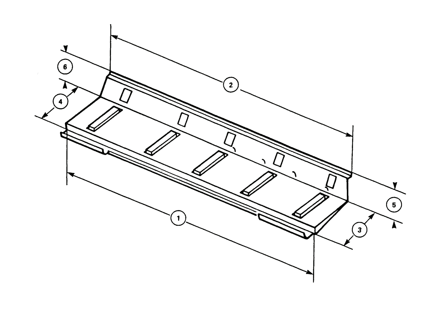
| Area No | Minumim Quantity | Length (mm) - Pitch (mm) | |
|---|---|---|---|
| Spot Welds | Plug Welds | Mig Welds | |
| 1 | 41 | ||
| 2 | 43 | ||
| 3 | 6 | ||
| 4 | 6 | ||
| 5 | Continuous | ||
| 6 | Continuous | ||
Figure 6-2-17 — Cowl PanelClick image to enlarge.
108.Removal — To remove, see Figure 6-2-17 and proceed as follows:
- Using a spot weld drill, remove welds in areas 1, 2, 3 and 4.
- Using a disc or pneumatic grinder, remove the continuous welds in areas 5 and 6.
- Using a pneumatic grinder and pliers, remove remnants from areas 1 through 4 of the vehicle.
- Separate the upper weld point of the door insert rail at the areas of the vehicle that correspond to areas 5 and 6 of the panel.
109.Installation — To install, see Figure 6-2-17 and proceed as follows:
- Using an angle grinder, grind all six areas of the new panel.
- Clamp the new panel into position at all six areas.
- Using a spot-welder, spot weld a single row at areas 1 and 2.
- Using MIG welding, plug weld areas 3 and 4.
- Using MIG welding, weld a continuous weld at areas 5 and 6.
- Using an pneumatic grinder, grind areas 3 through 6.
- Fill all externally visible welds with body-filler and sand in preparation for primer.
- Clean all remaining welds with a wire brush and sand in preparation for primer.
- Prime all repaired areas (refer to Section 3).
- Using PVC sealant (refer to Section 3), seal area 1.
- Paint the repaired areas (refer to Section 3).
- Apply bituminous preservative to cavities in the repaired area, (refer to Section 3).
Rear Panel

Figure 6-2-18 — LH Antenna Mount BossesClick image to enlarge.

Figure 6-2-19 — Plug Welds on Rear Wheel-Well PlateClick image to enlarge.

| Area No | Minumim Quantity | Length (mm) - Pitch (mm) | |
|---|---|---|---|
| Spot Welds | Plug Welds | Mig Welds | |
| 1 | 32 | ||
| 2 | 19 | ||
| 3 | 19 | ||
| 4 | 21 | ||
| 5 | 21 | ||
| 6 | 7 | ||
| 7 | 7 | ||
| 8 | Continuous | ||
| 9 | Continuous | ||
| 10 | 5 | ||
| 11 | 5 | ||
Figure 6-2-20 — Rear PanelClick image to enlarge.
110.Removal — To remove, proceed as follows:
CAUTION — Do not damage antenna mount threads when using a hole saw to cut rear panel from antenna mount.
- Using a 30 mm hole saw, cut the rear panel from the antenna mount bosses. There are five bosses on each side of the rear of the vehicle, see Figure 6-2-18.
- Using a plug weld drill, remove the plug welds which secure the rear wheelwell plate to the rear panel. Do not remove the plug welds indicated by arrows, which secure the antenna mounting plate to the rear panel, see Figure 6-2-19.
- Mark the position of each superstructure support mount on its side panel.
- Using a pneumatic grinder, remove the welds which secure each mount to the rear panel and rear side panel.
- Using a pneumatic chisel, chisel welds in areas 1 through 7, 10 and 11, see Figure 6-2-20.
- Using a pneumatic grinder, grind welds at areas 8 and 9.
- Using a pneumatic grinder, remove remnants from the areas of the vehicle that correspond to areas 1 through 11 of the panel.
- Using pliers, remove remnants from the areas of the vehicle that correspond to areas 1 through 7, 10 and 11 of the panel.
- Bend off welding edges from the areas of the vehicle that correspond to areas 2 and 3 of the new panel, remove remnants and realign.
111.Installation — To install, see Figure 6-2-20 and proceed as follows:
- Using a pneumatic grinder, grind areas 1 through 11 of the new panel.
- Position the panel on the vehicle and clamp in place at areas 1 through 11.
- Using a spot-welder, spot weld a single row at areas 1, 2, 3, 6, 7, 10 and 11.
- Using MIG welding, weld a continuous weld at areas 8 and 9.
- Using MIG welding, weld the rear panel to the antenna mount bosses. There are five bosses on each side of the rear of the vehicle, see Figure 6-2-18.
- Using MIG welding, weld the superstructure support mounts to the rear panel and the rear side panel, see Figure 6-2-19.
- Using MIG welding, plug weld the rear wheel-well plate to the rear panel, see Figure 6-2-19.
- Using a pneumatic grinder, grind areas 1, 2, 3 and the area around the antenna mounting bosses.
- Fill all externally visible welds with body-filler and sand in preparation for primer.
- Clean all remaining welds with a wire brush and sand in preparation for primer.
- Prime all repaired areas (refer to Section 3).
- Using PVC sealant (refer to Section 3), seal areas 1 through 7.
- Renew underbody PVC sealant (refer to Section 3), in the repaired areas.
- Paint the repaired areas (refer to Section 3).
- Apply bituminous preservative to cavities in the repaired area (refer to Section 3).
Rear Panel Crossmember

| Area No | Minumim Quantity | Length (mm) - Pitch (mm) | |
|---|---|---|---|
| Spot Welds | Plug Welds | Mig Welds | |
| 1 | 42 | ||
| 2 | 42 | ||
| 3 | 9 | 12-30 | |
| 4 | 9 | 12-30 | |
| 5 | 2 | ||
| 6 | 2 | ||
| 7 | 4 | ||
| 8 | 4 | ||
| 9 | 2 | ||
| 10 | 2 | ||
| 11 | 25-100 | ||
| 12 | 25-100 | ||
Figure 6-2-21 — Rear Panel CrossmemberClick image to enlarge.
112.Removal — To remove, see Figure 6-2-21 and proceed as follows:
- Using a pneumatic chisel, chisel welds in areas 3 through 12.
- Using a pneumatic grinder and pliers, remove remnants from the areas of the vehicle that correspond to areas 3 through 12 of the panel.
113.Installation — To install, see Figure 6-2-21 and proceed as follows:
- Using a pneumatic grinder, grind areas 1 through 10 of the new panel.
- Position the new crossmember on the vehicle and clamp into place at areas 3 through 10.
- Using a spot welder, spot weld a double row off-set at areas 1 and 2. Spot weld a single row at areas 3 through 10.
- Using MIG welding, weld and interrupted at areas 3, 4, 11 and 12.
- Fill all externally visible welds with body-filler and sand in preparation for primer.
- Clean all remaining welds with a wire brush and sand in preparation for primer.
- Prime all repaired areas (refer to Section 3).
- Using PVC sealant (refer to Section 3), seal areas 3 through 10.
- Renew underbody PVC sealant (refer to Section 3), in the repaired areas.
- Paint the repaired areas (refer to Section 3).
- Apply bituminous preservative to cavities in the repaired area (refer to Section 3).
Rear Side Panels

| Area No | Minumim Quantity | Length (mm) - Pitch (mm) | |
|---|---|---|---|
| Spot Welds | Plug Welds | Mig Welds | |
| 1 | Continuous | ||
| 2 | 5 | ||
| 3 | 2 | ||
| 4 | 29 | ||
| 5 | 19 | ||
| 6 | Continuous | ||
| 7 | 4 | ||
| 8 | 5 | ||
| 9 | Continuous | ||
| 10 | 12 | ||
| 11 | 19 | ||
| 12 | 5 | ||
| 13 | 2 | ||
| 14 | 9 | ||
| 15 | 2 | Continuous | |
| 16 | Continuous | ||
| 17 | Continuous | ||
Figure 6-2-22 — Rear Side PanelClick image to enlarge.
114.Removal — To remove, see Figure 6-2-22 and proceed as follows:
- Using a pneumatic chisel, chisel welds in areas 2 through 5, 7, 13 and 14.
- Using a disc or pneumatic grinder, grind welds in areas 6, 15 and 16.
CAUTION — When cutting the panel at area 1, do not damage the two reinforcement plates behind the panel.
- Using a pneumatic cutter, make a parting cut 20 mm at rear of the welding edge.
- Using a pneumatic grinder, remove remnants from the areas of the vehicle that correspond to areas 2 through 7, 13, 14, 15 and 16 of the panel.
- Using pliers, remove remnants from the areas of the vehicle that correspond to areas 1 through 5, 7, 13, and 14 of the panel. Do not remove remnants from area 15.
- Grind off weld points in area 5 cleanly so that the contact surface is not too severely damaged.
115.Installation — To install, see Figure 6-2-22 and proceed as follows:
- Using a disc or pneumatic grinder, grind areas 1 through 17 of the new panel.
- Using a spot welder, spot weld area 10 with area 11 and spot weld area 8 with area 12.
- Using a MIG welding, weld area 9 with 17.
- Position the new side panel and reinforcements on the side of the vehicle and secure the reinforcements to the panel. Remove the panel with reinforcements attached and weld the reinforcements to the panel.
- Position the panel on the vehicle and clamp into place at areas 1 through 7 and 15 through 17.
- Using a spot welder, spot weld a single row at areas 2 through 5, 7, 13 and 14.
- Using MIG welding, weld a continuous weld at areas 1, 6, 15, 16 and 17. Weld area 1 in stages and allow to cool between stages to reduce heat distortion.
- Using a disc grinder, grind welds at areas 1 through 10.
- Fill all externally visible welds with body-filler and sand in preparation for primer.
- Clean all remaining welds with a wire brush and sand in preparation for primer.
- Prime all repaired areas (refer to Section 3).
- Using PVC sealant (refer to Section 3), seal areas 2 through 17.
- Renew underbody PVC sealant (refer to Section 3), in the repaired areas.
- Paint the repaired areas (refer to Section 3).
- Apply bituminous preservative to cavities in the repaired area (refer to Section 3).
Rear Wheel-wells
| Area No | Minumim Quantity | Length (mm) - Pitch (mm) | |
|---|---|---|---|
| Spot Welds | Plug Welds | Mig Welds | |
| 1 | 16 | ||
| 2 | 16 | ||
| 3 | 6 | ||
| 4 | 10 | ||
| 5 | 22 | ||
| 6 | 6 | ||
| 7 | 9 | ||
| 8 | 9 | ||
| 9 | 15 | ||
| 10 | 6 | ||
| 11 | 14 | ||
| 12 | 2 | ||
| 13 | 7 | ||
| 14 | 4 | ||
| 15 | 5 | ||
| 16 | 7 | ||
| 17 | Continuous | ||
| 18 | 12 (2 required) | ||
Figure 6-2-23 — Rear Wheel WellClick image to enlarge.
116.Removal — To remove, see Figure 6-2-23 and proceed as follows:
- Using a pneumatic chisel, chisel welds at areas 7 through 13, 15 and 16.
- Using a disc or pneumatic grinder, grind welds at areas 14 and 18.
- Using a pneumatic cutter, make a parting cut 10 mm above the reinforcement plate at area 17.
- Using a pneumatic grinder, remove remnants from the areas of the vehicle that correspond to areas 7 through 18 on the panel.
- Using pliers, remove the remnants from the areas on the vehicle that correspond to areas 8 through 16 on the panel.
117.Installation — To install, see Figure 6-2-23 and proceed as follows:
- Using a disc or pneumatic grinder, grind areas 1 through 18 on the new panel.
- Drill 4 holes in area 14 of the panel for plug welding.
- Using a spot welder, spot weld a single row to weld together areas 1 and 2.
- Position the panel on the vehicle and clamp into place at areas 7 and 8.
- Using a spot welder, spot weld a single row at areas 7 through 13, 15 and 16.
- Using MIG welding, weld a continuous weld at area 17.
- Using MIG welding, weld an interrupted weld at area 18.
- Using MIG welding, plug weld at area 17.
- Fill all externally visible welds with body-filler and sand in preparation for primer.
- Clean all remaining welds with a wire brush and sand in preparation for primer.
- Prime all repaired areas (refer to Section 3).
- Using PVC sealant (refer to Section 3) seal areas 1, 2 and 7 through 18.
- Renew underbody PVC sealant (refer to Section 3), in the repaired areas.
- Paint the repaired areas (refer to Section 3).
- Apply bituminous preservative to cavities in the repaired area (refer to Section 3).
Section 3 — Maintenance and Adjustments
Diagnosis of Vehicles Involved in Accidents
1. Severe damage may occur to the running gear of vehicles involved in accidents. To prevent further damage as the result of damaged running gear, perform the following inspection:
NOTE — An inspection of suspension alignment also should be performed at this time.
- Check steering gear and steering linkage for correct operation over the entire steering range and inspect for distortion and cracks.
- Check drive axles, propeller shaft, wheel hubs, shock absorbers and wishbone arms for damage.
- Check wheels and tires for damage, true running and imbalance.
- Check tires for cuts in the tread and sidewalls.
- Ensure tire inflation pressure is correct.
- Check engine, transaxle, exhaust system and suspension for damage.
- Test drive the vehicle to check road worthiness.
Repairs to Body
2.Check the body for twisting or other damage. See Figure 6-3-1.
 |  |
 |  |
 |  |
 |  |
 |  |
| Dimension | Measurement (mm) | Description |
|---|---|---|
| A | 807 ± 6 mm | Distance between mounting holes for bonnet locking pins. |
| B | 1,406 ± 8 mm | Distance between outer edges of front wheel housings. |
| C | 1,480 ± 2 mm | Diagonal distance from inner side of wheel housing (juction with cowl panel) to outer edge of front wheel housing. |
| D | 946 ± 3 mm | Distance from front wheel housing outer edge to cowl panel. |
| E | 1,215 ± 3 mm | Distance from bottom of front wheel housing to front floor plate. |
| F | 1,412 ± 3 mm | Distance from front hinge pillar to rear side panel, front top edge, door opening. |
| G | 2,692 ± 3 mm | Diagonal distance from front hinge pillar to rear side panel, front top edge, door opening. |
| H | 1,205 ± 2 mm | Distance from rear floor plate to rear panel, lower outer edge. |
| J | 1,370 ± 2 mm | Distance between side panels, centre, measured at (inner) contact surface of roll bar mounting. |
| K | 1,370 ± 2 mm | Distance between side panels, rear, measured at (inner) contact surface of roll bar mounting. |
Figure 6-3-1 — Body DimensionsClick image to enlarge.
Repairs to Frame
3.Check the frame for twisting or other damage. See Figure 6-3-2 for frame dimensions.
 |
Click image to enlarge.
| Dimension | Measurement (mm) |
|---|---|
| a | 142 ± 5 mm |
| b | 222 ± 3 mm |
| c | 190 ± 5 mm |
| d | 76 ± 3 mm |
| e | 738 ± 3 mm |
| f | 1,150 ± 4 mm |
| g | 1,293 ± 5 mm |
| h | 1,708 ± 4 mm |
| j | 1,537 ± 5 mm |
Figure 6-3-2 — Frame Dimensions
Panel Corrosion Prevention (Bituminous)
4.General — The numbered symbols in Figure 6-3-3 show the location of existing holes where cavity preservative can be sprayed to prevent corrosion of the panels. The shaded areas show the location of panel cavities. Long term corrosion prevention is guaranteed if panel inner surfaces are coated with a complete protective film of preservative. For best results when applying preservative, move the spray hose slowly and evenly back and forth in each panel cavity. Each time a panel is straightened or replaced, apply preservative to the inner panel surface in the repaired area.
 Figure 6-3-3 — Panel CavitiesClick image to enlarge.
5.Application — To apply, proceed as follows:
WARNING — Rustproofing materials are flammable and toxic. To prevent fire or explosions, there must be no smoking, spark generation (welding, etc.) or open flames within 15 m (50 ft). Wear a protective respirator when spraying and cover exposed skin.
CAUTION — Spraying the following components may cause fire or overheating and damage:
- Exhaust system
- Radiator
- Engine
- Transaxle
- Rear Differential
- Brake Drums
- Insert the spray hose into the hood cavity and using reduced pressure, apply preservative.
- Insert the spray hose into each side panel reinforcement cavity and apply preservative.
- Insert the spray hose into each side panel bracing cavity and apply preservative.
- Insert the spray hose into each lower side panel bracing cavity and apply preservative.
- Insert the spray hose into each lower side panel reinforcement cavity and apply preservative.
- Insert the spray hose into each rear panel inner cavity and apply preservative.
- Insert the spray hose through the inside of the rear panel and into the rear panel outer cavity. Using reduced pressure, apply preservative.
- Insert and push the spray hose to the opposite end of the rear crossmember cavity and apply preservative.
- Insert and push the spray hose to the opposite end of the crossmember cavity under the rear floor panels and apply preservative.
- Insert and push the spray hose to the opposite end of the floor rear crossmember cavity and apply preservative.
- Remove the batteries, insert the spray hose into each rear floor panel cavity and apply preservative. Install the batteries.
Panel Corrosion Prevention (PVC)
6.General — The underside of replacement of repaired body panels must be protected with a PVC permanent underbody sealant.
WARNING — PVC and XYLOL solvent are flammable and toxic. To prevent fire or explosions, there must be no smoking, spark generation (welding, etc.) or open flames within 15 m (50 ft). Wear a protective respirator and cover exposed skin when applying PVC and XYLOL solvent.
7.Application — To apply, proceed as follows:
- Remove loose sealant using a spatula.
- Wash the surface with XYLOL solvent and allow to dry for 10 minutes.
- Apply SAHM-CHEMIE #VP-8919 PVC sealant to a minimum thickness of 0.3 mm, using a brush.
- Air dry for 24 hours before using vehicle.
Sealing Body Panel Joints
8.General — Body panel joints which are not continuously welded must be sealed with a PVC sealant.
9.Application — To apply, proceed as follows:
- Clean the area using sandpaper or a wire brush.
- Wash the surface with XYLOL solvent and allow to dry for 10 minutes.
- Apply SAHM-CHEMIE #VP-8919 PVC sealant to a thickness of 0.1 mm, using a brush.
Repairing the Protective Coating on Floor Interior
10.General — The floor interior is protected against abrasion by a coating of PVC.
11.Application — To apply, proceed as follows:
- Remove loose PVC, rust and dirt.
- Wash the surface with XYLOL solvent and allow to dry 10 minutes.
- Apply SAHM-CHEMIE #VP-8919 PVC sealant to a minimum thickness of 0.3 mm, using a brush.
Priming and Painting
12.Prime bare metal with epoxy primer MIL-P23377D.
13.Finish with Urethane enamel MIL-C-46168 (ME), colour specification D-84-010-001/SF-001.
14.Camouflage with Urethane enamel MILC-46168B (ME), see Figure 6-3-4.
 Areas color coded “O” — Olive Drab
Areas color coded “B” — Black
Areas color coded “G” — Green
Figure 6-3-4 — Body Camouflage PatternClick image to enlarge.
Body Mounting Bolts and Body Rubber Mounts
15.Using a 17 mm deep socket, remove the centre body mounting bolts and fibre washers from the two centre body mounts, see Figure 6-3-5. Apply lithium base grease to both sides of the washer and re-install. Torque the two mounting bolts and six remaining body mounting bolts to 45 N•m (33 ft lb). Inspect the mounting areas for cracks. This must be done every 7,500 km or once a year.
16.Ensure that all four body rubber mounts are secure. Tighten loose nuts using a 17 mm wrench, see Figure 6-3-5. There are two nuts on each mount which must be torqued to 45 N•m (33 ft lb). Inspect the mounting areas for cracks. This must be done every 7,500 km or once a year.
 Figure 6-3-5 — Body Mounting Bolts and Body Rubber MountsClick image to enlarge.
Section 4 — Troubleshooting
General
1.Figure 6-4-1 contains instructions on suspension troubleshooting.
| Item No | Malfunction | Probable Cause/Test | Corrective Action | ||
|---|---|---|---|---|---|
| 1. | Insufficient flexibility (hard ride) | a. | Tires over inflated. | a. | Reduce to proper pressure. |
| b. | Shock absorbers seized. | b. | Replace shocks. | ||
| c. | Overloaded vehicle. | c. | Reduce load. | ||
| 2. | Excessive flexibility | a. | Broken spring leaves. | a. | Replace broken leaves. |
| b. | Shock absorbers seized. | b. | Replace shocks. | ||
| 3. | Excessive noise when driving | a. | Loose “ U ” bolts. | a. | Tighten or replace. |
| b. | Broken centre bolt. | b. | Replace centre bolt. | ||
| c. | Broken spring leaf. | c. | Replace broken leaf. | ||
| d. | Worn spring bushings or bolts. | d. | Replace bushings or bolts. | ||
| e. | Missing rubber bump stop. | e. | Install bump stop. | ||
| f. | Worn wishbone bushings. | f. | Replace bushings. | ||
| g. | Loose or worn shock. | g. | Replace bushings or bolts. | ||
| h. | Worn, dirty or dry constant velocity joints (drive axle or propeller shaft). | h. | Repack or replace faulty CV joints. | ||
Figure 6-4-1 — Suspension Troubleshooting
Section 5 — Specifications and Special Tools
1.Figure 6-5-1 lists the torque specifications for all components in Part 6.
2.Figure 6-5-2 lists the special tools used in Part 6.
| Item No | Item or Component | N•m | ft lb |
|---|---|---|---|
| 1. | Body Mounting Bolts | 45 N•m | 33 ft lb |
| 2. | Light Guard to Bumper | 25 N•m | 18 ft lb |
| 3. | Pintle Hook to Frame | 60 N•m | 44 ft lb |
| 4. | Rifle Clip to Mount | 25 N•m | 18 ft lb |
| 5. | Rifle Block to Mount | 25 N•m | 18 ft lb |
| 6. | Roll Bar to Body | 35 N•m | 26 ft lb |
| 7. | Seat Belt Strap to Fender Well Panel (Rear) | 55 N•m | 41 ft lb |
| 8. | Seat Belt Buckle to Mount (Rear) | 55 N•m | 41 ft lb |
| 9. | Seat Belt End Plate and Reel to Mount (Front) | 55 N•m | 41 ft lb |
| 10. | Seat Belt Bracket to Roll Bar (Front) | 55 N•m | 41 ft lb |
| 11. | Seat Belt Buckle to Inner Mount (Front) | 55 N•m | 41 ft lb |
| 12. | Shock Absorber to Ball Joint | 200 N•m | 148 ft lb |
| 13. | Shock Absorber to Frame | 200 N•m | 148 ft lb |
| 14. | Spring to Trunnion | 90 N•m | 66 ft lb |
| 15. | Spring U-Bolts to Frame | 175-185 N•m | 129-136 ft lb |
| 16. | Spring Centre Bolt | 47 N•m | 35 ft lb |
| 17. | Tie-Rod to Spring Housing (Rear) | 60 N•m | 44 ft lb |
| 18. | Tie-Rod to Steering Arm (Rear) | 40 N•m | 30 ft lb |
| 19. | Wheel Bolts | 175 N•m | 129 ft lb |
| 20. | Wishbone Arm to Frame | 150 N•m | 111 ft lb |
Figure 6-5-1 — Body and Chassis Suspension Torque Specifications
| Item No | Tool No | Nomenclature | NATO Stock No. |
|---|---|---|---|
| 1. | 3030 | Pressing device | — |
Figure 6-5-2 — Special Tools