
C-30-108-000/MP-001 - First, Second and Third Line Maintenance Instructions — Part 5

1991-06-10 Ch 2695 Pages
PDF (12,573 KB)
For other Canadian Forces Technical Order (CFTO) documents, see Iltis-related Canadian Forces Technical Order Documents.

C-30-108-000/MP-001
First, Second and Third Line Maintenance Instructions — Part 5
Truck Utility, Light 4 x 4 Military Design Iltis Canadian Series
Issued on Authority of the Chief of the Defence Staff
OPI: DSVPM
1986-10-31
1991-06-10 Ch 2

WARNING — With the exception of the alternator and some minor components (e.g. composite taillight assemblies), all parts on the Iltis Canadian Series are dimensioned in the metric system. During any maintenance procedures, all replacement fasteners must have the same measurement and strength as those removed. (Numbers on the heads of metric bolts and on the surfaces of metric nuts indicate their strength). Mismatched or incorrect fasteners may result in personal injury or engine damage or malfunction. Therefore, fasteners removed from the engine should be saved for re-use in the same location where possible. When fasteners are unsatisfactory for re-use, care should be taken to select a replacement that matches the original.
Part 5 — Electrical System
Section 1 — General
General
Introduction
1.Part 5 consists of the following sections:
2.The charging and starting systems are dealt with in Part 2, Section 5.
Description of Electrical System
3.The vehicle has a 24-volt, negative-ground, electrical system that consists of the following:
- Two 12-volt batteries connected in series that supply power to all circuits on the vehicle.
- A multipolar, series-wound starter (refer to Part 2, Section 5, for description of starter).
- A heavy duty alternator (refer to Part 2, Section 5, for description of alternator).
- A slave receptacle can be used with a slave cable to start the vehicle, if the batteries are dead, or can be used to start another SMP vehicle with dead batteries. The connections are offset to prevent incorrect polarity connection. A jumper cable should not be used if a slave cable is available.
- There is a trailer receptacle on the rear of the vehicle for an intervehicular cable. The receptacle is used to connect the electrical system of the vehicle with a trailer for the operation of the trailer service lights and blackout tail-lights. Trailer lights are controlled by the master light switch in conjunction with the vehicle lights. The receptacle cover is held closed by a spring when the receptacle is not in use.
- A battery master switch controls all current from the batteries to the vehicle with the exception of the starter, alternator, slave receptacle and radio power supply box.
- The master light switch controls all lights on the vehicle with the exception of the warning lights, which are controlled by individual sending units. The master light switch must be “ON” for the warning lights to operate.
- The radio power supply box receives battery voltage at all times and is a means to connect radios to the battery supply. The outlets provide 24 volts to operate radios.
Operation of Electrical System
4.When the accessory switch is moved to the “ON” position, current from the batteries flows to the ignition circuit and accessories circuit. With the accessory switch in either the “ON” or “OFF” position, current from the batteries flows to the alternator, starter, and fan thermoswitches. Caution must be taken when working around these components. The radio power supply box is on a separate circuit with the batteries and receives battery current at all times.
Description of Circuit Breakers
5.The electrical system is protected by six circuit breakers. The breaker panel is located on the rear of the switch panel. The breakers protect the following circuits:
- Horn;
- Radiator Fans (Left and Right);
- Wiper Motor;
- Blower Motor;
- Fuel Pump.
The radio outlet circuit is protected by a separate breaker located in the radio power supply box which is mounted on the inside of the rear panel.
Description of Lighting System
6.Power for the lighting system is provided by the battery or charging system, depending on battery charge and alternator charging rate. Turn signals are controlled by a switch on the steering column.
Description of Sending Units
7.Changes in temperature or pressure vary the electrical resistance of the sending units. These electrical changes are indicated by units of measurement on the gauges or by the illumination of warning lights. The sending units are mounted in the area being monitored.
Wiring Harnesses
8.The chassis wiring harnesses are made up of cables, connectors, plugs, receptacles and terminals needed to carry power to electrical components. They terminate in connector plugs, connector receptacles and/or cable terminals. A trailer electrical receptacle is provided. The harnesses are secured to the vehicle by plastic clips.
Section 2 — Component Removal and Installation
General
WARNING — Do not replace metric bolts with standard bolts. See WARNING page at the front of the manual.
General
1.Section 2 describes electrical circuit components, and their removal, inspection and installation.
WARNING — Due to their higher power capabilities, the following procedures must be observed before beginning any tests on a 24 volt system.
Do not permit a “hot” wire to touch metal parts of the vehicle at any time. “Flash” testing by striking a hot wire against a vehicle ground will cause an arc that will completely destroy the connector on the lead.
Accidental contact of metal tools between battery or starter cables and the frame of the vehicle will cause a direct short circuit. This will result in arcing and instant heating of the tools to red hot. This can cause painful burns to the hands and serious damage to tools, vehicle components and batteries. Moreover, the overloaded battery may explode, spraying hot acid and sharp fragments over the surrounding area.
WARNING — To prevent injury, ensure the battery ground cable terminal of the left battery is disconnected before removing or installing electrical components. When switched off, the battery master switch does not disconnect the alternator, starter, slave receptacle or radio power supply box.
Horn
2.Removal — To remove, proceed as follows:
- Check the horn as per the troubleshooting guide (refer to Section 3).
- Turn off the battery master switch.
- Disconnect the two terminal connectors from the horn.
- Remove the two cap screws securing the horn and bracket to the fender.
- Remove the horn and the mounting bracket.
- Remove the securing nut from the back of the horn and remove the horn from the bracket.
3.Installation — To install, proceed as follows:
- Install the horn to the mounting bracket.
- Install the horn and bracket to the fender with the two cap screws.
- Connect terminal connectors 25A and 91G to the horn.
- Turn on the battery master switch, and test the horn.
Oil Temperature Sending Unit
4.Removal — To remove, proceed as follows:
- Disconnect the electrical wire from the sending unit.
- Remove the sending unit from the oil filter housing.
5.Installation — To install, proceed as follows:
- Install a new copper washer on the sending unit and install the sending unit in the oil filter housing.
- Connect electrical wire #34 to the sending unit terminal.
- Test for operation.
Oil Pressure Sending Unit
6.Removal — To remove, proceed as follows:
- Disconnect the electrical wires from the sending unit.
- Remove the sending unit from the cylinder head.
7.Installation — To install, proceed as follows:
CAUTION — To prevent damage to the sending unit, do not overtighten during installation.
- Install a new copper washer on the sending unit and install the sending unit in the cylinder head and tighten.
- Connect electrical wires #35 and #36 to the sending unit terminals.
- Test for operation.
Coolant Temperature Sending Unit (Gauge)
8.Removal — To remove, proceed as follows:
WARNING — To prevent injury, allow the engine to cool before removing the cap from the expansion reservoir.
- Remove the cap from the expansion reservoir to relieve pressure in the cooling system.
- Disconnect the wire from the coolant temperature gauge sending unit.
- Remove the sending unit from the housing.
NOTE — A small amount of coolant will be lost when the sending unit is removed.
9.Installation — To install, proceed as follows:
- Install the sending unit into the sending unit housing.
- Connect electrical wire #33 to the sending unit terminal.
- Add coolant to the expansion reservoir until the coolant level is correct and install the expansion reservoir cap.
- Test for operation.
Coolant Temperature Warning Light Sending Unit
10.Removal — To remove, proceed as follows:
WARNING — To prevent injury, allow the engine to cool before removing the cap from the expansion reservoir.
- Remove the cap from the expansion reservoir to relieve the pressure in the cooling system.
- Disconnect the electrical wire from the warning light sending unit.
- Remove the sending unit from the housing.
NOTE — A small amount of coolant will be lost when the sending unit is removed.
11.Installation — To install, proceed as follows:
- Install the sending unit in the housing.
- Connect electrical wire #32 to the sending unit terminal.
- Add coolant to the expansion reservoir until the coolant level is correct and install the expansion reservoir cap.
- Test for operation.
Two-wheel Drive Sending Unit
12.General — The two-wheel drive sending unit consists of a microswitch which activates the two-wheel drive warning light when the differential of the transaxle is disengaged.
13.Removal — To remove, proceed as follows:
- Check the sending unit as per the troubleshooting guide (refer to Section 3).
- Disconnect the two wires from the sending unit.
- Remove the sending unit from the front differential housing.
14.Installation — To install the two-wheel drive sending unit, proceed as follows:
CAUTION — Do not overtighten the sending unit. It is made of aluminium and is easily damaged.
- Install a new unit in the differential housing.
- Connect wires #80 and #91F to the sending unit.
- Test for operation.
Rear Differental Lock Sending Unit
15.General — The rear differential lock sending unit consists of a switch mounted on the differential which is activated when the differential lock is engaged. A red warning light on the dash is lit when the differential is locked.
16.Removal — To remove, proceed as follows:
- Check the sending unit as per the troubleshooting guide (refer to Section 3).
- Disconnect the wires from the sending unit.
- Remove the sending unit from the rear differential housing.
17.Installation — To install, proceed as follows:
CAUTION — Do not overtighten the sending unit. It is made of aluminium and is easily damaged.
- Install a new unit in the differential housing.
- Connect wires #82 and #90D to the sending unit.
- Test for operation.
Brake Light Switch
18.Removal — To remove, proceed as follows:
- Turn off the battery master switch.
- Disconnect the electrical leads from the switch terminals.
- Remove the switch from the master cylinder.
19.Installation — To install, proceed as follows:
- Install the switch in the master cylinder.
- Connect electrical leads #75 and #75A to the switch terminals.
- Bleed the master cylinder.
- Turn on the battery master switch.
- Test for operation.
Hand Brake Warning Light Switch
20.Removal — To remove, proceed as follows:
- Check the switch as per the troubleshooting guide (refer to Section 3).
- Disconnect wires #90A and #22A from the switch.
- Remove the two screws.
- Remove the switch.
21.Installation — To install, proceed as follows:
- Install the switch, ensuring the switch lever goes under the brake cable yoke.
- Install the switch, using the two screws.
- Connect wire #90A to the rear terminal.
- Connect wire #22A to the front terminal.
- Test the hand brake warning light.
Battery Master Switch
22.Removal — To remove, proceed as follows:
- Check the switch as per the troubleshooting guide (refer to Section 3).
- Disconnect the battery ground cable.
- Remove the two Philips-head machine screws, lock washers and nuts from the switch.
- Remove the switch from the bracket. Remove the nuts and lock washers from the cable posts, and disconnect the cables.
23.Installation — To install, proceed as follows:
CAUTION — Ensure the cables are connected to the correct posts before connecting the battery ground cable. Consult the wiring diagram, see Figure 5-2-9, at the end of this section, if necessary.
- Install the cables to the posts with the lock washers and nuts.
- Install the battery, master switch into the bracket and secure with two Phillips-head machine screws, lock washers and nuts.
- Connect the battery ground cable.
- Test for operation.
Slave Receptacle
24.Removal — To remove, proceed as follows:
- Check the slave receptacle as per the troubleshooting guide (refer to Section 3).
- Disconnect the battery ground cable.
- Remove the four machine screws and lock washers that secure the receptacle to the mounting bracket.
- Remove the battery master switchfrom the mounting bracket.
- Disconnect the slave positive (+) cable #15 from the battery master switch.
- Disconnect the ground cable #50 from the body (left of the receptacle).
- Remove the positive cable from the securing clips at the rear of the dash, and along the right side of the vehicle.
- Disconnect the positive cable from the positive battery terminal.
- Remove the receptacle from the bracket and remove the cable from the vehicle.
25.Installation — To install, proceed as follows:
- Feed the long positive cable behind the dash and along the right side to the battery.
- Install the cable in the retaining clips.
- Install the positive cable #15 to the battery master switch.
- Install the battery master switch on the mounting bracket.
- Install the ground cable #50 and the two other ground cables to the body.
- Install the slave receptacle on its mounting bracket with four machine screws and lock washers.
- Connect the positive cable to the positive battery terminal.
- Connect the battery ground cable to the battery ground terminal.
- Test for operation.
Master Light Switch
26.Removal — To remove, proceed as follows:
- Check the light switch as per the troubleshooting guide (refer to Section 3).
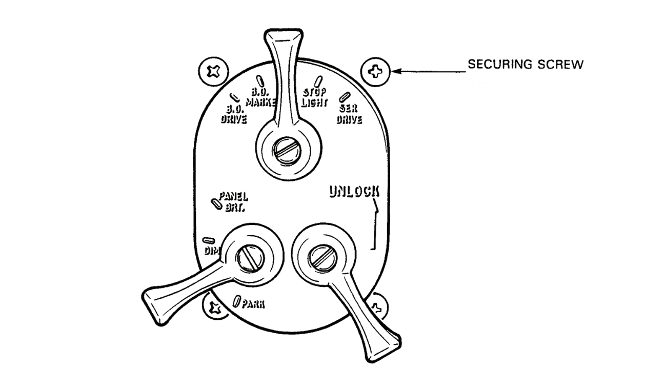
Figure 5-2-1 — Master Light Switch Securing ScrewsClick image to enlarge.
- Disconnect the battery ground cable.
- Remove the switch panel from the dash.
- Remove the harness locking collar from the rear of the switch and remove the harness connector from the light switch.
- Remove the three screws and lock washers that secure the three light switch levers and remove the levers.
- Remove the four securing screws from the master light switch, see Figure 5-2-1, and remove the switch from the panel.
27.Installation — To install, proceed as follows:
- Insert the master light switch through the rear of the switch panel.
- Install the four securing screws.
- Install the three light switch levers with screws and lock washers.
- Connect the harness connector to the rear of the switch ensuring the slot in the connector aligns with the lug on the bottom of the switch receptacle.
- Install the harness locking collar on the receptacle and tighten until it is fully home.
- Install the switch panel on the dash.
- Connect the battery ground cable.
- Test the switch to ensure it functions correctly.
Accessory Switch
28.General — The accessory switch controls the current to the light switch, gauges and indicators and to the starter button, horn switch, fuel pump, windshield wiper motor switch and heater blower motor switch as well as the ignition system.
29.Removal — To remove, proceed as follows:
- Check the switch as per the troubleshooting guide (refer to Section 3).
- Turn off the battery master switch.
- Remove the switch panel from the dash.
- Remove the lever from the switch assembly.
- Remove the nut, lock washer, and switch identification plate.
- Disconnect the four bayonet-type connectors from the switch.
- Remove the switch from the panel.

Figure 5-2-2 — Accessory Switch ConnectorsClick image to enlarge.
30.Installation — To install, proceed as follows:
- Connect the four bayonet-type connectors to the switch, see Figure 5-2-2. Connect wire #11 at the top right (“A”), wire #27 at top left (“B”), wire #2A at bottom left (“D”) and wire #11 at bottom right (“C”).
NOTE — Both #11 wires splice into the same single wire.
- Install the accessory switch in the switch panel, ensuring the locating pin is engaged in the hole in the panel.
- Install the identification plate with “OFF” at the 12 o'clock position.
- Install the nut and lock washer.
- Install the accessory switch lever with the screw and lock washer, ensuring the flats in the lever align with the flats on the switch shaft.
- Turn on the battery master switch and test the accessory switch.
Turn Signal Lights and Hi-Lo Beam Control Lever and Windshield Wiper Control

Figure 5-2-3 — Turn Signal Lights and Hi-Low Beam Control Lever Securing ScrewsClick image to enlarge.
31.Removal — To remove, proceed as follows:
- Turn off the battery master switch.
- Remove the steering wheel (refer to Part 4, Section 1).
- Remove the lower and upper steering column covers and the inner dust cover.
- Disconnect the three electrical connectors from the control levers.
- Remove the three securing screws, see Figure 5-2-3, and remove the control levers.
32.Installation — To install, proceed as follows:
- Install the control levers with three screws.
- Connect the electrical connectors to the control levers.
- Install the upper and lower steering column covers and the inner dust cover.
- Install the steering wheel (refer to Part 4, Section 1).
- Turn on the battery master switch.
- Test for operation.
Starter Button
33.Removal — To remove, proceed as follows:
- Turn off the battery master switch.
- Remove the switch panel from the dash.
- Loosen the inner dust cover clamp at the top of the steering column covers.
- Remove the two screws from the lower steering column cover and remove the lower cover.
- Disconnect the starter button electrical connector.
- Remove the locking nut and washer from the starter button.
- Disconnect the turn signal/horn multiple connector.
- Remove the starter button from the bracket and dash.
34.Installation — To install, proceed as follows:
- Connect the starter button electrical connector.
- Turn on the battery master switch and accessory switch and test the start button.
- Turn off the battery master switch.
- Disconnect the wires and install the starter button wires through the dash and over the steering column.
- Connect the electrical connectors.
- Insert the button into the bracket and install the lock washer and nut. Do not overtighten.
- Connect the signal/horn multiple connector.
- Install the lower steering column cover.
- Tighten the inner dust cover clamp.
- Install the switch panel to the dash.
- Turn on the battery master switch.
Heater/Hazard Switch Assembly
35.General — The heater control and hazard light switches share the same receptacle. The receptacle is secured to the dash by two spring clips.
36.Removal — To remove, proceed as follows:
- Check the switches as per the troubleshooting guide (refer to Section 3).
- Turn off the battery master switch.
- Remove the gauge panel.
- Pry the heater/hazard light switch assembly from the dash.
- Remove the red multiple connector from the top of the hazard light switch and the single connector from the bottom.
- Remove the white and red multiple connector from the bottom of the heater switch and the two single black connectors from the top.
37.Installation — To install, see Figure 5-2-4 and proceed as follows:
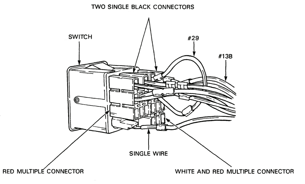
Figure 5-2-4 — Heater/Hazard Switch ConnectorsClick image to enlarge.
- Connect the white and red multiple connector to the bottom of the heater switch and the two single black connectors to the top. The heater switch is at the left side of the assembly.
- Connect the single wire to the connector at the bottom of the hazard light switch.
- Connect the red multiple connector to the top of the 'hazard light switch.
- Install the heater/hazard switch assembly in the dash. Push in the assembly until the retaining clips engage.
- Turn on the battery master switch.
- Test the operation of the heater and hazard lights.
Gauge Panel
38.General — The gauge panel supports the oil pressure gauge, the coolant temperature gauge and the battery/alternator indicator gauge. The panel is secured to the dash by four quick disconnect fasteners.
39.Removal — To remove, proceed as follows:
- Turn off the battery master switch.
- Unfasten the four one-quarter-turn panel fasteners, and pull the gauge panel from the dash.
40.Installation — To install, proceed as follows:
- With the gauges installed, position the panel in the dash.
- Secure the gauge panel to the dash with the four one-quarter-turn fasteners.
- Turn on the battery master switch.
NOTE — To remove the individual gauges, follow the procedures described below for each gauge.
Oil Pressure Gauge
41.Removal — To remove, proceed as follows:
- Check the gauge as per the troubleshooting guide (refer to Section 3).
- Remove the gauge panel.
- Disconnect the multiple connector from the bottom of the gauge.
- Remove the light and light holder from the rear of the gauge.
- Remove the two knurled securing nuts and the securing bracket.
- Remove the gauge through the panel front.
42.Installation — To install, proceed as follows:
- Insert the back of the gauge through the front of the panel.
- Position the securing bracket over the two mounting screws.
- Install the two knurled nuts on the mounting screws.
- Connect the multiple connector to the bottom of the gauge.
- Install the light holder and light.
- Install the gauge panel.
Coolant Temperature Gauge
43.Check the gauge as per the troubleshooting guide (refer to Section 3). For removal and installation, follow the same procedures for the oil pressure gauge.
Battery/Alternator Indicator
44.Check the gauge as per the troubleshooting guide (refer to Section 3). For removal and installation, follow the same procedures for the oil pressure gauge.
Warning Lights
45.General — The hand brake, rear differential lock and two-wheel drive warning lights are located on the dash above the gauge panel. Access to the rear of the lights is through the gauge panel opening. The removal and installation procedure is the same for all three warning lights.
46.Removal — To remove, proceed as follows:
- Check the warning light as per the troubleshooting guide (refer to Section 3).
- Remove the gauge panel.
- Remove the bulb holder from the dash.
- Remove the bulb.
47.Installation — To install, proceed as follows:
- Install a new bulb in the holder.
- Install the bulb and holder in the dash.
- Install the gauge panel.
Radio Receptacle Power Supply Box
48.Removal — To remove, proceed as follows:
- Check the power supply box as per the troubleshooting guide (refer to Section 3).
- Disconnect the battery ground cable.
- Disconnect and remove the radios.
- Remove the six self-locking nuts from the power supply box.
- Remove the box from the rear panel and turn it around for easy access.
- Disconnect the positive and negative wires.
- Remove the supply box from the vehicle.
49.Installation — To install, proceed as follows:
- Connect the positive wire to the positive terminal and negative wire to the negative terminal in the supply box.
- Install the supply box to the inside of the rear panel with the six self-locking nuts.
- Connect the battery ground cable.
Trailer Receptacle
50.Removal — To remove, proceed as follows:
- Check the receptacle as per the troubleshooting guide (refer to Section 3).
- Turn off the battery master switch.
- Remove the four cap screws that secure the receptacle door to the housing.
- Remove the four cap screws that secure the mounting bracket to the vehicle body.
- Remove the harness locking collar from the back of the trailer receptacle.
- Remove the grommet and slide it onto the wires, out of the way.
- Using needle nosed pliers, remove the terminals from the receptacle and tag the wires for reinstallation.
51.Installation — To install, proceed as follows:
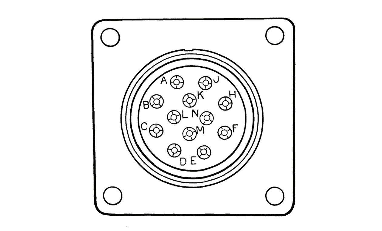
- Match up and insert tagged terminals into the receptacle, see Figure 5-3-11.
- Slide the grommet down the wires and insert it into the receptacle.
- Install the harness locking collar on the rear of the receptacle.
- Install the mounting bracket to the vehicle body with the four cap screws.
- Install the receptacle door on the housing so that the door swings upwards.
- Turn on the battery master switch.
Wiring and Harnesses
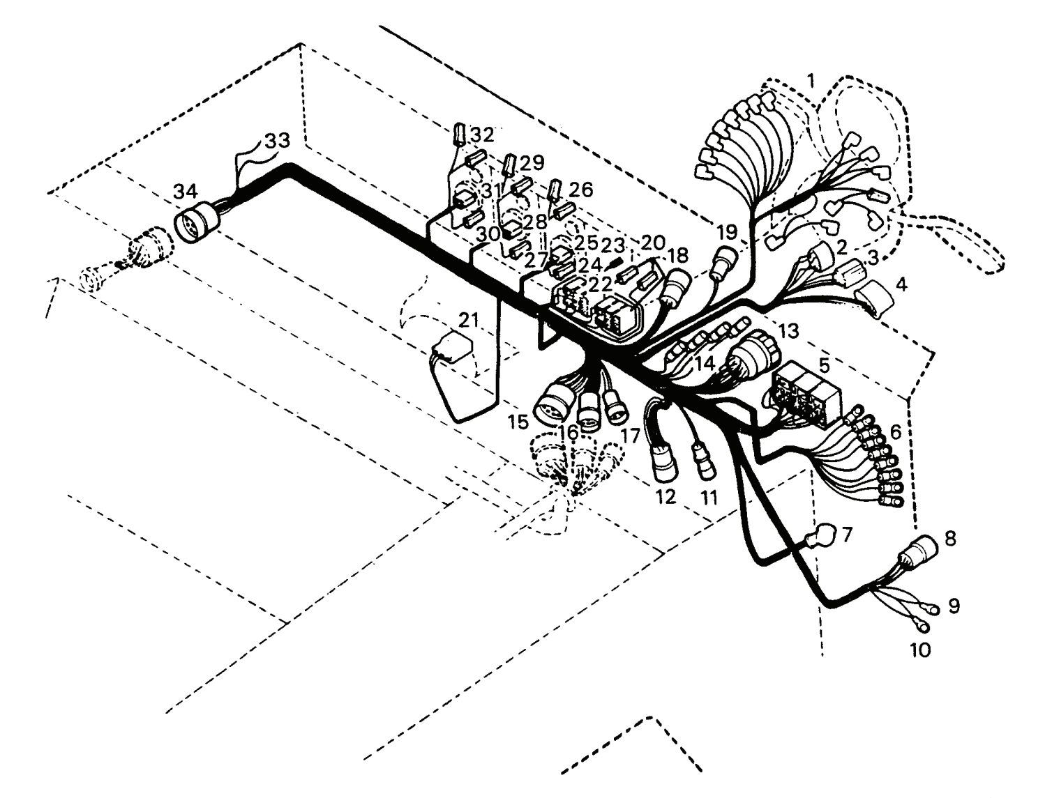
52.General — The different circuits can be identified by reference to the wiring diagrams. All terminals are identified with circuit numbers, see Figure 5-2-5, Figure 5-2-6 and Figure 5-2-7. For the electrical system schematic, see Figure 5-2-9.

| Legend No | Component | Wire No | Wire Connection Point |
|---|---|---|---|
| 1. | Right front harness connector under dash, right side | 37B | 1 - Starter. |
20 | 2 - Blackout Marker. | ||
491 | 3 - Park Light. | ||
91D | 4 - Park Light. | ||
18 | 5 - Headlight — Low Beam. | ||
17 | 6 - Headlight — Low Beam. | ||
460 | 7 - Right Turn Signal | ||
1C | 8 - Fuel Cutoff Valve. | ||
74A | 9 - Starter. | ||
| 2. | Ballast resistor under hood, left side | 37A | Resistor Interconnecting Wire. |
37B | Resistor to Starter. | ||
37 | Resistor to Coil Suppressor. | ||
27B | Resistor from Accessory Switch. | ||
| 3. | Ignition circuit connector under dash, left side | 1 | 1 - D+ Alternator. |
27A | 2 - Transistorized Ignition Unit. | ||
37B | 3 - Ballast Resistor. | ||
| 4. | Sending unit connector under dash, left side | 80 | 1 - Two-Wheel Drive Switch. |
33 | 2 - Coolant Temperature Sensor. | ||
36 | 3 - Oil Pressure Sensor. | ||
22B | 4 - Brake Fluid Level Switch. | ||
35 | 5 - Oil Pressure Switch. | ||
51 | 6 - Windshield Washer Motor. | ||
34 | 7 - Oil Temperature Switch. | ||
| 5. | Left front harness connector under dash, left side | 18 | 1 - Headlight. |
17 | 2 - Headlight. | ||
461 | 3 - Signal Light. | ||
20 | 4 - Blackout Marker. | ||
491 | 5 - Park Light. | ||
19 | 6 - Blackout Drive Light. | ||
75 | 7 - Brake Light Switch. | ||
75A | 8 - Brake Light Switch. | ||
25A | 9 - Horn. | ||
| 6. | Fan circuit breakers under dash, left side | 84 | Left Fan. |
85 | Right Fan. | ||
| 7. | Battery master switch | 1D | To Alternator Regulator terminal. |
| 8. | Ground point — Left cab floor | 52 | Alternator Ground Point. |
| 9. | Ground point — Left fender wall | 91D | Engine Ground. |
95 | |||
| 10. | TCI unit socket — Firewall | 27A | A - From Accessory Switch. |
95 | B - Ground. | ||
| 11. | Windshield washer motor — Left fender wall | 51 | From Wiper Control. |
91K | Ground. | ||
| 12. | Coil suppressor — Left fender wall | 37 | From Ballast Resistors. |
| 13. | Brake light switch — Under master cylinder | 75 | To Master Light Switch. |
75A | To Master Light Switch. | ||
| 14. | Brake fluid level switches — Tops of brake fluid reservoirs | 22C | Front to Rear Reservoir. |
91J | Front to Rear Reservoir. | ||
22B | To Brake Warning Light. | ||
91H | Ground. | ||
| 15. | Two-wheel drive switch — Right side transaxle | 80 | To Warning Light. |
91F | Ground. | ||
| 16. | Coolant temperature switch — Coolant temperature sensor | 32 | To Coolant Temperature Light. |
33 | To Coolant Temperature Gauge. | ||
| 17. | Oil pressure switch — Oil pressure sensor | 35 | To Oil Pressure Light. |
36 | To Oil Pressure Gauge. | ||
| 18. | Oil temperature switch — On oil filter base | 34 | To Oil Temperature Light. |
| 19. | Alternator | 1 | D+ to Cutout Relay. |
1D | To Battery Master Switch. | ||
2 | B+ to Starter. | ||
52 | Ground. | ||
| 20. | Horn | 25A | To Horn Relay. |
91G | Ground. | ||
| 21. | Starter | 2 | To Alternator. |
6 | From Slave Receptacle. | ||
37B | From Ballast Resistors. | ||
74A | From Starter Button. | ||
| 22. | Air/Fuel cutoff valve | 1C | From Accessory Switch. |
| 23. | Ground Point — Right fender wall | 91 | Right Head Light. |
91C | Right Blackout Marker. | ||
91D | Right Harness Ground. | ||
91B | Right Turn Signal Light. | ||
91A | Right Parking Light. | ||
| 24. | Right front turn signal | 91B | Ground 22 Right Fender. |
460 | Brake and Signal Flasher Unit. | ||
| 25. | Right headlight | 17 | High Beam from Dimmer Switch. |
18 | Low Beam from Dimmer Switch. | ||
91 | Ground 22 Right Fender. |
||
| 26. | Right park light | 91A | Ground 22 Right Fender. |
491 | From Master Light Switch. | ||
| 27. | Right blackout marker | 20 | From 24 at Master Light Switch. |
91C | Ground 22 Right Fender. |
||
| 28. | Right cooling fan | 85A | From Bottom Thermoswitch. |
96C | Ground to Fan Bracket. | ||
96B | Ground to 31 Left Fender. |
||
| 29. | Left cooling fan | 84A | From Top Thermoswitch. |
96A | Ground to Fan Bracket. | ||
96 | Ground to 31 Left Fender. |
||
| 30. | Left fan thermoswitch | 84 | From Circuit Breaker. |
84A | To Left Fan Motor. | ||
| 31. | Right fan thermoswitch | 85 | From Circuit Breaker. |
85A | To Right Fan Motor. | ||
| 32. | Ground point — Left fender wall | 91 | Left Headlight. |
91A | Left Park Light. | ||
91C | Left Blackout Marker. | ||
91D | Left Harness Ground. | ||
91E | Left Blackout Drive Light. | ||
96 | Left Cooling Fan. | ||
96B | Right Cooling Fan. | ||
91B | Left Turn Signal Ground. | ||
| 33. | Left park light | 491 | From Master Switch. |
91A | Ground to 31 Left Fender. |
||
| 34. | Left headlight | 17 | High Beam from Dimmer Switch. |
18 | Low Beam from Dimmer Switch. | ||
91 | Ground to 31 Left Fender. |
||
| 35. | Left signal light — Front body | 461 | From Brake and Signal Flasher. |
91B | Ground. | ||
| 36. | Blackout drive light | 19 | From Master Light Switch. |
91E | Ground to 31 Left Fender. |
||
| 37. | Left blackout marker | 20 | From Master Light Switch. |
91C | Ground to 31 Left Fender. |
Figure 5-2-5 — Front Wiring HarnessClick image to enlarge.
| Legend No | Component | Wire No | Wire Connection Point |
|---|---|---|---|
| 1. | Speedometer head (see also figure 5-2-8 | 460A | Turn Signal Warning Light To Signal Flasher Unit. |
461A | Turn Signal Warning Light To Signal Flasher Unit. | ||
467B | Trailer Signal Warning Light To Signal Flasher Unit. | ||
35 | Oil Pressure Light to Oil Pressure Switch. | ||
93E | Ground to Speedo Head Lug. | ||
17 | High Beam Indicator Light To Dimmer Switch. | ||
28 | Fuel Gauge from Sending Unit. | ||
27F | Fuel Gauge from Accessory Switch. | ||
81F | Oil Temp. Light from 81E. |
||
81E | Coolant Temperature Light from 81D. |
||
81D | Oil Pressure and Alternator Light from Warning Light Relay. | ||
34A | Alternator Light to Diode. | ||
1B | Alternator Light to Alternator D+ Relay. | ||
32B | Coolant Light. | ||
32 | Coolant Temperature Light to Coolant Temperature Switch. | ||
34B | Oil temperature Light to Diode. | ||
34 | Oil Temperature Light to Oil Temperature Switch. | ||
40 | Left Hand Dash Lights. | ||
40A | Right Hand Dash Lights. | ||
| 2. | Turn signal and horn button switch | 60 | To brake and Signal Flasher. |
463 | To Emergency Flasher Switch 49A. |
||
61 | To Brake and Signal Flasher. | ||
25B | To Horn Relay 85. |
||
| 3. | Windshield wiper control | 51 | Wiper Switch to Wiper Motor. |
53 | Wiper Switch to Wiper Motor 53. |
||
53A | Wiper Switch to Wiper Motor 53A. |
||
53B | Wiper Switch to Wiper Motor 53B. |
||
53E | Wiper Switch to Wiper Motor 53E. |
||
| 4. | Dimmer switch | 16 | To Master Light Switch. |
16A | To Splice at #460/461. |
||
17 | To High Beam Indicator Light. | ||
18 | To Headlights. | ||
| 5. | Relays under Dash — Left to right horn relay | 25B | To Horn Button. |
25A | To Horn. | ||
25 | To Horn Circuit Breaker. | ||
25 | Interconnecting Wire to 25 Horn Circuit Breaker. |
||
| Alternator D+ cutout relay | 1A | From Warning Light Relay. | |
1 | To Alternator D+. | ||
1B | To Alternator Warning Light. | ||
93H | To Ground Point 11. |
||
93K | To Warning Light Relay. | ||
| Relay warning light relay | 2A | From Accessory Switch. | |
2B | From Splice at 460/461 at Master Light Switch. |
||
1A | To Cutout Relay Alternator D+. | ||
81D | To Feed Alternator and Oil Pressure Lights. | ||
93K | From Cutout Relay. | ||
| 6. | Circuit breakers from left to right 1. Fuel pump 2. Left hand coolant fan 3. Right hand coolant fan 4. Horn 5. Windshield wiper motor 6. Heater blower motor | 83A | To Fuel Pump Circuit Breaker. |
12 | To Left Hand Fan Circuit Breaker. | ||
12A | To Right Hand Fan Circuit Breaker. | ||
25 | From Horn Circuit Breaker. | ||
10 | To Horn Circuit Breaker. | ||
50 | From Wiper Circuit Breaker. | ||
50A | To Wiper Circuit Breaker. | ||
13 | From Heater Blower Circuit Breaker. | ||
13A | To Heater Blower Circuit Breaker. | ||
| 7. | Battery master switch | 1D | To Alternator Regulator Terminal. |
15 | To Splice for Accessory Switch and Terminal “F” of Master Light Switch. |
||
15 | From Slave Receptacle. | ||
| 8. | Connector to rear harness | 82 | 1 - To Differential Lock Switch. |
22A | 2 - To Hand Brake Switch. | ||
28 | 3 - To Fuel Level Sending Unit. | ||
23 | 4 - To Blackout Stop Lights. | ||
21 | 5 - To Service Tail-lights. | ||
24 | 6 - To Blackout Tail-lights. | ||
| 9. | Ground point | 91D | Dash Harness Ground. |
94 | Wiper Motor Ground. | ||
| 10. | Ground point | 93E | Ground for Dashlights, Trailer Signal Warning Light, High Beam Indicator Light. |
93 | Ground for Alternator D + Cutout Relay, Brake/Turn Signal Flasher Unit, Emergency Flasher Switch and Light, Blower Motor and Switch, Battery Generator Indicator, Coolant Temperature Gauge, Oil Pressure Gauge, Map Reading Light, Battery Generator Indicator Light, Coolant Temperature and Oil Pressure Gauge Lights. | ||
| 11. | Brake/Turn signal flasher unit | 460 | To Right Front Signal Light. |
461 | To Left Front Signal Light. | ||
| 12. | Brake/Turn signal flasher unit | 93 | 1 - To Ground Point 10. |
60 | 2 - To Turn Signal Switch. | ||
61 | 3 - To Turn Signal Switch. | ||
467B | 4 - Trailer Turn Signal Warning Light. | ||
467 | 5 - To Turn Signal Switch. | ||
2C | 6 - To Splice at Wire 460/461 at Master Light Switch. |
||
22 | 7 - To Master Light Switch. | ||
| 13. | Master light switch | 75 | A - Stop Light Feed. |
40 | B - Instrument Panel Feed. | ||
22 | C - Service Stop Light. | ||
19 | D - Blackout Drive Light. | ||
24 | E - Blackout Marker and Tail-lights. | ||
15 | F - Light Switch Feed from Master Switch. | ||
21 | H - Service Tail-light. | ||
460/461 | J - Front Turn Signals. | ||
75A | K - From Stop Light Switch. | ||
491 | L - Parking Lights. | ||
16 | M - Dimmer Switch Feed. | ||
23 | N - Blackout Stop Light. | ||
| 14. | Accessory switch | 11 | A - From Splice at Wire 15. |
11 | C - Battery Master Switch. | ||
27 | B - Feed to All Circuits. | ||
2A | D - Feed to Circuit Breakers and Relays. | ||
| 15. | Left front light connector | 18 | 1 - To Headlight Low Beam. |
17 | 2 - To Headlight High Beam. | ||
461 | 3 - Turn Signal Light. | ||
20 | 4 - To Blackout Marker. | ||
491 | 5 - To Parking Light. | ||
19 | 6 - Blackout Drive Light. | ||
75 | 7 - Stop Switch Feed. | ||
75A | 8 - From Stop Light Switch. | ||
25A | 9 - To Horn. | ||
32 | 10 - To Coolant Temperature Light. | ||
| 16. | Sending unit connector | 80 | 1 - Two Wheel Drive Light. |
33 | 2 - From Coolant Temperature Gauge. | ||
36 | 3 - From Coolant Temperature Gauge. | ||
22B | 4 - From Brake Warning Light. | ||
35 | 5 - From Oil Pressure Light. | ||
51 | 6 - From Washer Switch. | ||
34 | 7 - From Oil Temperature Light. | ||
| 17. | Starting circuit connector | 1 | 1 - To Alternator D+ Relay. |
27A | 2 - From Accessory Switch to Ballast Resistor. | ||
37B | 3 - From Ballast Resistor to Starter. | ||
| 18. | Wiper motor connector | 53A | 1 - From Wiper Switch 53A. |
53E | 2 - From Wiper Switch 53E. |
||
53 | 3 - From Wiper Switch 53. |
||
53B | 4 - From Wiper Switch 53B. |
||
94 | 5 - From Ground Point 9. |
||
| 19. | Starter button connector | 74 | 1 - From Accessory Switch Splice. |
74A | 2 - To Starter Solenoid 50. |
||
| 20. | Heater blower switch connector | 13 | 1 - To Blower Motor Circuit Breaker. |
13B | 2 - Blower Switch Connector to Blower Motor. | ||
29 | 3 - To Blower Motor. | ||
29A | 4 - To Blower Motor. | ||
| 21. | Heater blower motor connector | 29 | 1 - From Blower Motor Switch. |
29A | 2 - From Blower Motor Switch. | ||
93B | 3 - To Ground. | ||
| 22. | Emergency flashing connector | 460/461 | To Light Switch 49. |
460B | To Turn Signal Light 49A. |
||
467 | To Turn Signal 30. |
||
463 | To Turn Signal Switch 15A. |
||
| 23. | Emergency flasher ground | 93A | Ground to Ground Point 10. |
| 24. | Oil pressure gauge light | 40B | From Splice at Dash Light Wire 40. |
40C | To Coolant Temperature Gauge Light. | ||
| 25. | Oil pressure gauge | 27D | To Coolant Temperature Gauge. |
27C | From Wire #27 Ignition. |
||
36 | To Oil Pressure Sensor. | ||
93C | Ground to Ground Point 10. |
||
93D | To Coolant Temperature Gauge. | ||
| 26. | Brake warning light | 22B | To Brake Fluid Level Switch 22B. |
81 | From Warning Light Relay. | ||
81A | To Differential Lock Light. | ||
| 27. | Coolant temperature gauge light | 40C | From Oil Pressure Gauge Light. |
40D | To Battery Generator Indicator Light. | ||
| 28. | Coolant temperature gauge | 27E | To Battery Generator Indicator. |
27D | From Oil Pressure Gauge. | ||
33 | To Coolant Temperature Sensor. | ||
93D | From Oil Pressure Gauge. | ||
93E | To Battery Generator Indicator. | ||
| 29. | Differential lock warning light | 81A | From Brake Warning Light. |
81B | To Two Wheel Drive Warning Light. | ||
82 | To Differential Lock Switch. | ||
| 30. | Battery generator indicator light | 40D | To Indicator Light. |
| 31. | Battery generator indicator | 27E | From Coolant Temperature Gauge. |
93E | To Coolant Temperature Gauge. | ||
| 32. | Two-wheel drive warning light | 80 | To Light Switch. |
81B | From Differential Lock Warning Light. | ||
| 33. | Map reading light | 81C | From Splice at 460/461 at Emergency Flasher Switch. |
93C | Ground to Ground Point 10. |
||
| 34. | Right front harness | 37B | 1 - Starter 15A to Resistors. |
20 | 2 - To Blackout Marker. | ||
491 | 3 - To Parking Light. | ||
91D | 4 - Ground to Ground Point 9. |
||
18 | 5 - Headlight Low Beam. | ||
17 | 6 - Headlight High Beam. | ||
460 | 7 - Turn Signal. | ||
1C | 8 - Air/Fuel Cutoff Valve. | ||
74A | 9 - From Starter Button. |
Figure 5-2-6 — Dash Wiring HarnessClick image to enlarge.

| Legend No | Component | Wire No | Wire Connection Point |
|---|---|---|---|
| 1. | Right rear composite light | 90 | Ground. |
21 | Right Tail-light. | ||
22-460 | Right Stop and Signal. | ||
24 | Right Blackout Marker. | ||
23 | Right Blackout Stop. | ||
| 2. | Trailer recepticle | 490 | H - Blackout Markers. |
22-460 | J - Right Stop and Signal. | ||
22-461 | B - Left Stop and Signal. | ||
24 | A - Blackout Markers. | ||
24 | C - Blackout Markers. | ||
21 | E - Tail-lights. | ||
23 | F - Blackout Stop. | ||
90 | D - Ground. | ||
| 3. | Left rear Composite light | 90 | Ground. |
23 | Left Blackout Stop. | ||
24 | Left Blackout Marker. | ||
22-461 | Left Stop and Signal. | ||
21 | Left Tail-light. | ||
| 4. | Licence plate light | 90B | Ground. |
26 | Licence Plate Light. | ||
| 5. | Ground | 90F | Ground. |
| 6. | Fuel level transmitter | 90E | Ground. |
28 | Fuel Level Gauge. | ||
| 7. | Differential lock switch | 90D | Ground. |
82 | Differential Lock Warning Light. | ||
| 8. | Fuel pump | 90C | Ground. |
83 | Fuel Pump Circuit Breaker. | ||
| 9. | Hand brake warning light switch | 90A | Ground. |
22A | Brake Warning Light. | ||
| 10. | Brake and turn signal unit — under dash | 22-460 | 1 - Right Stop and Signal. |
22-461 | 2 - Left Stop and Signal. | ||
3 - Blank. |
|||
| 11. | Under dash | 83 | Fuel Pump Circuit Breaker. |
| 12. | Under dash | 90 | Ground. |
| 13. | Rear harness connector under dash | 82 | 1 - Differential Lock Switch. |
22A | 2 - Hand Brake Switch. | ||
28 | 3 - Fuel Level Transmitter. | ||
23 | 4 - Blackout Stop Lights. | ||
21 | 5 - Tail-lights. | ||
24 | 6 - Blackout Markers. |
Figure 5-2-7 — Rear Wiring HarnessClick image to enlarge.

| Item No | Wire No | Circuit |
|---|---|---|
| 1. | 28 | Fuel gauge sending unit. |
| 2. | 27F | Fuel gauge accessory switch. |
| 3. | 40/40A | Speedometer light. |
| 4. | 34/34B and 81F | Oil temperature warning light. |
| 5. | 32/32B and 81E/81F | Coolant temperature warning light. |
| 6. | 34A/1B | Alternator warning light. |
| 7. | 460A | Turn signal indicator light (right turn). |
| 8. | 81D/81E | Alternator light and oil pressure light. |
| 9. | 461A | Turn signal indicator light (left turn). |
| 10. | 35 | Oil pressure warning light. |
| 11. | 467B | Trailer turn signal indicator light. |
| 12. | 17 | High beam indicator light. |
| 13. | 40A | Speedometer light. |
| 14. | 93E | Ground. |
Figure 5-2-8 — Speedometer Head Electrical TerminalsClick image to enlarge.

| Sym | Nomenclature |
|---|---|
⊛ 3 | Radio Power Supply Box |
⊛ 2 | Brake/Turn Signal Flasher Unit |
⊛ 1 | TCI Unit |
Z1 | Ignition Supressor |
W1 | Distributor |
S21 | Differential Lock Switch |
S20 | Starter Button |
S19 | Wiper Motor Switch |
S18 | Hand Brake Warning Light Switch |
S17 | Battery Master Switch |
S16 | Master Light Switch |
S15 | Accessory Switch |
S14 | Hi-Lo Beam Switch |
S13 | Horn Button Switch |
S12 | Turn Signal Switch |
S11 | Emergency Flasher Switch |
S10 | Blower Switch |
S9 | Brake Light Switch |
S8 | Brake Fluid Level Switch |
S7 | Brake Fluid Level Switch |
S6 | Oil Temperature Sending Unit |
S5 | Oil Pressure Sending Unit |
S4 | Coolant Temperature Sending Unit |
S3 | Two-Wheel Drive Light Switch |
S2 | Fan Thermo Switch |
S1 | Fan Thermo Switch |
RT2 | Oil Pressure Sending Unit |
RT1 | Coolant Temperature Sending Unit |
R3 | Fuel Level Sending Unit |
R2 | Ballast Resistor |
R1 | Ballast Resistor |
P10 | Male Connector |
P9 | Male Connector |
P8 | Male Connector |
P7 | Male Connector |
P6 | Male Connector |
P5 | Male Connector |
P4 | Male Connector |
P3 | Male Connector |
P2 | Male Connector |
P1 | Male Connector |
M4 | Gasoline Gauge |
M3 | Oil Pressure Gauge |
M2 | Coolant Temperature Gauge |
M1 | Battery/Alternator Indicator |
LS1 | Horn |
L2 | Ignition Coil |
L1 | Air/Fuel By-Pass Valve |
K3 | Relay - Warning Lights |
K2 | Relay - Cut-Out Alternator D+ |
K1 | Relay - Horn |
J12 | Slave Receptacle |
J11 | Female Connector |
J10 | Female Connector |
J9 | Female Connector |
J8 | Female Connector |
J7 | Female Connector |
J6 | Female Connector |
J5 | Female Connector |
J4 | Female Connector |
J3 | Female Connector |
J2 | Female Connector |
J1 | Female Connector |
G1 | Alternator |
E4 | Spark Plug |
E3 | Spark Plug |
E2 | Spark Plug |
E1 | Spark Plug |
D,CR3 | Diode |
D,CR2 | Diode |
D,CR1 | Diode |
DS35 | Indicator Light for Hazard Warning Light |
DS34 | License Plate Light |
DS33 | LH Parking Light |
DS32 | LH Stop & Turn Signal |
DS31 | LH Blackout Maker Light |
DS30 | LH Blackout Stop Light |
DS29 | LH Blackout Stop Light |
DS28 | RH Blackout Marker Light |
DS27 | RH Stop & Turn Signal |
DS26 | RH Parking Light |
DS25 | High Beam Indicator Light |
DS24 | Turn Signal Warning Light (Trailer) |
DS23 | Dash Light |
DS22 | Dash Light |
DS21 | Turn Signal Indicator Light |
DS20 | Coolant Temperature Warning Light |
DS19 | Oil Temperature Warning Light |
DS18 | Alternator Warning Light |
DS17 | Oil Pressure Warning Light |
DS16 | Oil Pressure Gauge Light |
DS15 | Coolant Temperature Gauge Light |
DS14 | Battery/Alternator Gauge Light |
DS13 | Brake Warning Light |
DS12 | Differential Lock Warning Light |
DS11 | Two-Wheel Drive Light |
DS10 | Map Reading Light |
DS9 | LH Front Turn Light |
DS8 | LH Head Light |
DS7 | LH Parking Light |
DS6 | LH Blackout Marker Light |
DS5 | LH Blackout Drive Light |
DS4 | RH Blackout Marker Light |
DS3 | RH Head Light |
DS2 | RH Parking Light |
DS1 | RH Front Turn Light |
CB7 | Circuit Breaker - Radio Box |
CB6 | Circuit Breaker - Heater Fan |
CB5 | Circuit Breaker - Wiper |
CB4 | Circuit Breaker - Horn |
CB3 | Circuit Breaker - RH Radiator Fan |
CB2 | Circuit Breaker - LH Radiator Fan |
CB1 | Circuit Breaker - Fuel Pump |
BT2 | Battery |
BT1 | Battery |
B7 | Fuel Pump |
B6 | Wiper Motor |
B5 | Blower Motor |
B4 | Windshield Washer Pump |
B3 | Starter Motor |
B2 | RH Fan Motor |
B1 | LH Fan Motor |
Figure 5-2-9 — Electrical System SchematicClick image to enlarge.
Section 3 — Troubleshooting
General
1.The tests and inspections are illustrated and presented step by step. They must be done in the order shown. These procedures suggest corrective action to take when a faulty component is found.
2.Wiring diagrams for the truck electrical system are used to supplement the tests and inspections. See Figure 5-2-5, Figure 5-2-6, Figure 5-2-7 and Figure 5-2-9.
3.When troubleshooting the lighting system, always look for dirty or corroded lamp sockets and connectors. Also look for pins which have been bent, broken or pushed back in their connectors. Clean, straighten or tighten connectors or lamp sockets, as needed, before replacing light bulbs or other parts.
Multimeter and Ohms Scale
4.When using the multimeter on the ohms scale, disconnect the battery ground cable terminal from the negative post of the left battery and disconnect the circuit being tested. The ohms scale is used for making tests for continuity, shorts and resistance. Proceed as follows:
CAUTION — Failure to disconnect the battery ground cables can result in damage to the multimeter. The battery master switch does not disconnect all vehicle circuits when switched off.
- The multimeter must be set-up and “zeroed” before making any tests.
NOTE — If the needle will note “zero” replace multimeter batteries. If the needle still will not “zero” after replacing batteries, replace the test leads or the meter.
- Voltage Scales — If the voltage range is not known, select a range higher than required and move the selector to the next lower scale until a reading is obtained.
- The red test probe must always be connected to the most positive side of the circuit.
General Notes
5.When connecting a meter probe to ground, make sure the ground point picked is a clean, unpainted area of the engine or body.
Electrical System Troubleshooting
6.Figure 5-3-1, Figure 5-3-2, Figure 5-3-3, Figure 5-3-4, Figure 5-3-5, Figure 5-3-6, Figure 5-3-7, Figure 5-3-8, Figure 5-3-9, Figure 5-3-10, and Figure 5-3-11, are tabulations of procedures for tests and inspections, with corrective actions for overcoming malfunctions in the electrical system. Calibration of meters used is covered in preceding paragraph 4.
Figure 5-3-1 — Steering System Troubleshooting
1. One or both headlights will not light. (All other lights are working.)
Test 1:
Disconnect the socket from the headlight bulb. Turn light switch to “SERVICE DRIVE”. Connect the positive probe to either wire #17 or #18.
- If the meter reads battery voltage (23-25 volts), replace the headlight bulb.
- If the meter shows no reading (0 volts), check the other wire or lift up on the dimmer switch lever once.
- If the meter now reads battery voltage, replace the headlight bulb.
- If the meter still shows no reading, do Test 2.
Test 2:
Remove the cover from the steering column. Disconnect the socket with the four wires from under the directional signal lever. Touch the positive probe to socket terminal #16. Reinstall the socket.
- If the meter reads battery voltage, the dimmer switch is N/S and must be replaced.
- If there is no voltage indicated, check the master light switch, do Test 3.
Test 3:
Remove the switch panel from the dash. Remove the connector from the light switch. Connect a jumper wire between terminal “F” and terminal “M” of the wire connector (see Figure 5-3-2).
- If the headlights now operate, replace the master light switch.
- If the lights still do not come on, repair or replace wire #16 between the connector and the dimmer switch.
2. Blackout drive, front blackout markers, park light or front turn signal will not light.
Test 1:
Disconnect the wire from the back of the light that is not working. Turn the light switch (and turn signal lever if necessary) to the position which matches the light being tested. Connect the positive probe to the disconnected wire.
- If meter reads battery voltage, replace the bulb (meter will fluctuate between 0 and battery voltage, if testing signal lights).
- If meter shows no reading (0 volts) when checking the turn signals, do Test 2 malfunction item 4.
- If the meter shows no reading (0 volts) when testing lights other than the signal lights, do Test 2.
Test 2:
Remove the switch panel from the dash. Remove the connector from the light switch. Connect a jumper wire from socket “F” to the socket of the light that is not working. (Also depress the brake pedal or move the turn signal control lever if checking those lights).
- Repair or replace the wiring between the light switch and either right or left connector.
3. Rear lights will not operate.
Test 1:
Disconnect the wire from the back of the light that is not working.
| Wire no. | Circuit |
|---|---|
21 | Service Taillights. |
22-460 | Service Stop and Turn Signal light - right. |
22-461 | Service Stop and Turn Signal light - left. |
23 | Blackout Stop-light. |
24 | Blackout Marker. |
26 | Licence Plate Marker. |
Connect the positive probe to the wire. Turn the light switch, and the turn signal lever if necessary, to the position that matches the light being tested. Also depress the brake pedal, if checking service or blackout brake lights.
- If the meter reads battery voltage, replace the bulb. (Meter fluctuates between 0 volts and battery voltage if checking signal lights).
- If meter shows no reading (0 volts), do Test 2.
Test 2:
Remove the light panel from the dash. If checking the stop-light or turn signals, disconnect the two wire plug with wires marked #22-460 and #22-461. If checking other lights, disconnect the connector with 6 wires #82, 22A, 28, 23, 21, 24.
Connect the positive probe to the connector pin or socket of the light being checked on the front connector.
| Wire No. | Circuit | Pin No. |
|---|---|---|
22-460 | Service Stop and Turn Signal light - right. | 1 |
22-461 | Service Stop and Turn Signal light - left. | 2 |
21 | Service Taillights. | 5 |
23 | Blackout Stoplight. | 4 |
24 | Blackout Marker. | 6 |
28 | Fuel-level Sending Unit. | 3 |
22A | Handbrake Switch | 2 |
82 | Differential Lock Switch. | 1 |
NOTE — The licence plate wire #26 splices into wire #21 at the left rear of the vehicle.
Turn the light switch, and turn signal lever if necessary, to the position which matches the light being tested. Depress the brake pedal if checking brake lights.
- If the meter reads battery voltage, repair or replace the rear wiring harness or the wire at fault.
- If the meter shows no reading when checking service stoplights or turn signals, do Test 3.
- When checking lights other than service stoplights or turn signals, and the meter shows no reading, see malfunction item 4.
Test 3:
Disconnect the seven wire connector at the turn/brake signal unit. Connect the positive probe to connector pins #2 and then #3 on the wire connector not attached to the signal unit. Move the signal lever for a left and right turn. Ensure light switch is in service drive or stop position.
- If the meter shows battery voltage, replace the turn/brake signal unit.
- If the meter shows no voltage, do Test 4.
Test 4:
Remove the steering column bottom cover Remove the three, wire connectors from the bottom of the signal lever. Connect the positive probe to the connector socket for wire #463.
- If meter shows battery voltage, repair or replace the wiring between the signal lever and the turn/brake signal unit and check the signal lever. Replace, if necessary.
- If there is no voltage shown on the meter, do Test 5.
Test 5:
Remove the emergency flasher unit from the dash. Pull the connector socket from the switch. Connect the positive probe to connector socket for wire 460/461.
- If there is battery voltage, replace the emergency flasher switch.
- If there is no voltage, do Test 6.
Test 6:
Remove the connector from the master light switch. Ensure the directional signal lever is in right or left position and the connector is connected. Connect a jumper wire between sockets “J” and “F” of the wire connector.
- If the signal lights now operate, replace the master light switch.
- If they still do not operate, repair or replace wire
#460/461between the light switch and the emergency flasher switch.
4. All or some lights do not operate.
Ensure there is battery voltage through the battery master switch by sounding the horn, operating the windshield wipers, or starting the engine.
- If there is no voltage, check the battery master switch, the batteries and cables.
- If there is voltage, do Test 1.
Test 1: Checking Voltage to Master Light Switch.
Remove the switch panel from the dash. Remove the connector from the light switch. Connect the positive probe to socket “F” in the connector.
- If there is no reading, repair or replace wiring harness or wire #15 between the light switch and the tie point.
- If there is battery voltage, do Test 2.
Test 2: Checking Voltage Through the Master Light Switch.
Connect a jumper wire from socket “F” to the light that is not working. (Also depress the brake pedal or move the turn signal control lever if checking those lights). See Figure 5-3-2.
- If the light that did not work now lights, replace the light switch.
- If the light still does not work, repair or replace:
- The wiring between the light switch and the brake light switch, if checking the stoplights.
- The wiring between the light switch and the emergency flasher switch.
- The wiring between the light switch and the rear connector, if checking other rear lights.
- The wiring between the light switch and dimmer switch, if checking the headlights.
- The wiring between the light switch and either right or left connector, if checking other front lights.
Figure 5-3-1 — Steering System Troubleshooting

| Socket | Wire No | Circuit |
|---|---|---|
A | 75 | Service stoplight switch |
B | 40 | Dash lights |
C | 22 | Service stoplights |
D | 19 | Blackout drive light |
E | 24 | Blackout marker lights |
F | 15 | Battery-positive 24Vdc input |
H | 21 | Tail-lights |
J | 460/461 | Signal lights |
K | 75A | Service stoplight switch |
L | 491 | Park lights |
M | 16 | Headlights |
N | 23 | Blackout stoplight |
Figure 5-3-2 — Master Light Switch ConnectorsClick image to enlarge.
Figure 5-3-3 — Instruments and Gauges Troubleshooting
1. All gauges do not work
No voltage to instrument panel.
Test 1:
Remove instrument panel. Disconnect wire #27C, 27D or 27E from either gauge. Turn accessory switch “ON”. Set multimeter to 60 Vdc scale. Connect positive probe to disconnect wire. Connect negative probe to good ground.
- If meter reads battery voltage (23 to 25 volts), check instrument panel ground wire
#93. - If meter shows no reading, do Test 2.
Test 2: Accessory Switch Wiring
Remove accessory/light switch panel. Disconnect wire #27 from accessory switch. Turn accessory switch “ON”. Connect positive probe to wire #27 terminal “B” on the switch.
- If meter reads battery voltage (23 to 25 volts), check wiring between accessory switch and instrument panel
#27. - If meter shows no reading, do Test 3.
Test 3: Accessory Switch Wire
Reconnect #27 wire. Disconnect both #11 wires. Connect positive probe to each #11 wire.
- If meter shows no reading (0 volts) for either wire, repair or replace wires
#11or#10between master switch and accessory switch. - If meter reads 23 to 25 volts, do Test 4.
Test 4: Accessory Switch
Disconnect all wires from the switch. Connect an ohmmeter between the terminals “A” and “B” and between “C” and “D”. Turn “ON” the switch.
- If there is no continuity in the switch, replace the switch.
2. Battery generator indicator does not work
Test 1:
Remove and connect instrument panel to good ground. Disconnect wire plug from back of gauge. Turn accessory switch “ON”. Connect positive probe to #27E wire.
- If meter reads battery voltage (23 to 25 volts), do Test 2.
- If meter shows no reading, repair or replace wiring between accessory switch and indicator.
Test 2:
Set the meter switch to the RX1 ohm scale. Connect the meter probes to each of the indicator terminals.
- If the meter reads less than 1 ohm, replace the indicator.
- If the meter reads more than 1 ohm, remove the indicator from the instrument panel. Clean the surface where the panel and indicator contact and reinstall the indicator. Check it is okay (lets than 1 ohm) and if the indicator still does not work, replace the indicator.
Figure 5-3-3 — Instruments and Gauges Troubleshooting
Figure 5-3-4 — Warning Lights Troubleshooting
1. Warning lights do not work
Defective warning light bulbs.
- Check bulb and replace if necessary.
Check for voltage at the relay (see Figure 5-3-6) and check relay.
- No voltage, check wiring to relay.
- Replace relay if necessary.
- Voltage to relay, if relay okay, check applicable warning light sending unit and wiring.
2. Warning light stays on
Defective sending unit.
- Check and repair or replace applicable unit.
Figure 5-3-4 — Warning Lights Troubleshooting
Figure 5-3-5 — Horn Troubleshooting
1. Horn does not work
Test 1:
Disconnect wire #25A from horn. Connect meter positive probe to wire. Depress horn button.
- If there is voltage, replace the horn.
- If there is no voltage, do Test 2.
Test 2:
Remove switch panel. Remove left relay (see Figure 5-3-6). Using meter, check voltage at wire terminal 25.
- If there is no voltage, check wire
#25to circuit breaker, circuit breaker and wire #10 from circuit breaker to ignition tie-point. Repair or replace faulty wire or circuit breaker. - If there is voltage, check the continuity through the relay.
- If there is no continuity, replace the relay.
- If there is continuity, clean or replace the contact in the horn switch or the
#25Bwire to the switch.
Figure 5-3-5 — Horn Troubleshooting

| Wire No | Circuit |
|---|---|
1 | Alternator D+ |
1A | Warning light via 81D |
1B | Alternator warning light |
2A | Accessory switch |
2B | Master light switch |
25 | Horn circuit breaker |
25A | Horn |
25B | Horn switch |
81D | Warning lights |
93H | Ground |
93K | Ground via 93H |
Figure 5-3-6 — RelaysClick image to enlarge.
Figure 5-3-7 — Heater Blower Troubleshooting
1. Heater blower does not operate.
Test 1:
Remove the light switch panel from the dash. With accessory switch “ON”, check for battery voltage to and from the circuit breaker. Wire #13 and 13A on the circuit breaker nearest to the light switch.
- If there is no voltage to the circuit breaker, check wire
13Ato the breaker and the accessory switch. - If there is voltage to the circuit breaker but none from it, replace the circuit breaker.
- If there is voltage from the circuit breaker, do Test 2.
Test 2:
Remove the blower switch from the dash. Remove the connector from the switch. With the accessory switch “ON”, connect the positive probe to connector socket wire #13.
- If there is no voltage, repair or replace the wire between the switch and the circuit breaker.
- If there is battery voltage, do Test 3.
Test 3:
Turn the switch to low speed and then to high speed. Check for voltage at wire socket #29A and then #29.
- If there is no voltage, replace the switch.
- If there is voltage at only one speed, replace the switch.
- If there is no voltage at one or both sockets, do Test 4.
Test 4:
Reconnect the socket connector to the switch and reinstall the switch in the dash. Disconnect wire #29 from the heater motor. With the accessory switch “ON”, connect the positive probe to the wire socket.
- If there is no voltage, repair or replace the
#29wire between the switch and the motor. - If there is battery voltage, replace the motor.
Figure 5-3-7 — Heater Blower Troubleshooting
Figure 5-3-8 — Windshield Washer Motor and Pump Troubleshooting
1. Windshield wiper motor does not operate.
Test 1:
Ensure the connector on the motor is secure and socket and terminal pins are clean.
- Clean and secure if necessary.
- If motor does not run, do Test 2.
Test 2:
Remove connector plug from the motor. Connect the positive probe to the lower left socket of the wire connector. Turn “ON” the accessory switch and the wiper control lever.
- If the meter reads battery voltage, replace the wiper motor.
- If there is no reading, do Test 3.
Test 3:
Remove the light switch panel. Turn “ON” the accessory switch. Using a meter, connect the positive probe to wire #50A and then to wire #50 of the second circuit breaker from the right.
- If there is no voltage at
#50A, replace wire#50Afrom the circuit breaker to tie-point or to#27of the accessory switch. - If there is voltage at
#50Aand none at#50, replace the circuit breaker. - If there is voltage at
#50, do Test 4.
Test 4:
Remove the steering column lower cover. Pull the connector from the wiper lever. Turn “ON” the accessory switch. Using a meter, connect the positive probe to the socket of wire #53A.
- If there is no voltage, replace wire
#53Ato tie-point or directly to the circuit breaker. - If there is voltage, do Test 5.
Test 5:
Reconnect the connector to the wiper arm Disconnect the wire connector from the wiper lever and the wiper motor under the dash by the steering column. Using a meter, connect the red probe to wire connector socket #3 or wire #53 of the wire coming from the lever. Turn the accessory switch and the wiper lever on.
- If there is no voltage, replace the wiper lever or the wire from the lever to the connector.
- If there is voltage, replace the wire from the connector to the motor.
2. Windshield wiper operates on one speed only.
Test 1:
Pull connector from the wiper motor. Using a meter, connect the positive probe to either socket of the two upper wire sockets. (Top left for fast and top right for slow.) Position the lever to testing speed. Turn accessory switch “ON”.
- If there is voltage, replace the wiper motor.
- If there is no voltage, remove the cable and check continuity through the wires.
- If wire is faulty, replace wire.
- If wire is okay, replace the wiper control lever.
3. Windshield washer does not work (wipers work).
Probable Cause - Fluid reservoir empty.
- Refill.
Probable Cause - Fluid hose to spray nozzle or nozzle plugged.
- Remove hose from pump and blow through hose to check. Unblock, if necessary.
Test 1:
Remove wire #51 from the pump. Connect meter positive probe to wire. Turn accessory switch “ON” and activate pump lever.
- If there is voltage, replace the pump.
- If there is no voltage, do Test 2.
Test 2:
Remove the steering column bottom cover. Remove the connector from the wiper lever. Check for continuity through wire #51.
- If there is no continuity, check and repair broken wire.
- If there is continuity, replace the wiper lever control.
Figure 5-3-8 — Windshield Washer Motor and Pump Troubleshooting
Figure 5-3-9 — Fuel Pump Troubleshooting
1. Fuel pump does not work.
Test 1:
Check for voltage at wire #83 at the fuel pump.
- If there is voltage, replace the pump.
- If there is no voltage, do Test 2.
Test 2:
Remove the switch panel. Check for voltage to the circuit breaker, wire #83A (farthest breaker to left).
- If there is no voltage, repair or replace wiring to accessory switch.
- If there is voltage, check wire
83Aat breaker. If there is no voltage, replace the breaker. If there is voltage, repair or replace the wiring to the pump.
Figure 5-3-9 — Fuel Pump Troubleshooting
Figure 5-3-10 — Trailer Power Outlet Receptacle Troubleshooting
1. Trailer lights will not operate.
Test 1:
Turn master light switch on. Turn on directional signals and depress brake pedal, if checking these lights. Connect negative probe of meter to trailer receptacle socket “D” and connect the positive probe to the socket of the light being checked (see Figure 5-3-11).
- If meter shows battery voltage, problem is in trailer wiring.
- If meter shows no voltage, do Test 2.
Test 2:
Leave positive probe connected. Connect negative probe to good ground on frame.
- If meter shows voltage, clean ground and check
#90wire. - If meter shows no voltage, replace the receptacle or faulty wire.
Figure 5-3-10 — Trailer Power Outlet Receptacle Troubleshooting
| Socket | Wire No | Circuit |
|---|---|---|
A | 24 | Blackout marker light |
B | 22-461 | LH stop and flasher light |
C | 24 | Blackout marker light |
D | 90 | Ground |
E | 21 | Parking light |
F | 23 | Blackout stop light |
H | 490 | Blackout marker light |
J | 460/461 | RH stop and flasher light |
K,L,M,N | — | Unused |
Figure 5-3-11 — Trailer Power Outlet Receptacle ConnectorClick image to enlarge.