This is an old revision of the document!

C-30-108-000/MP-001 - First, Second and Third Line Maintenance Instructions — Part 3

1991-06-10 Ch 2695 Pages
PDF (12,573 KB)

C-30-108-000/MP-001
First, Second and Third Line Maintenance Instructions — Part 3
Truck Utility, Light 4 x 4 Military Design Iltis Canadian Series
Issued on Authority of the Chief of the Defence Staff
OPI: DSVPM
1986-10-31
1991-06-10 Ch 2

WARNING — With the exception of the alternator and some minor components (e.g. composite taillight assemblies), all parts on the Iltis Canadian Series are dimensioned in the metric system. During any maintenance procedures, all replacement fasteners must have the same measurement and strength as those removed. (Numbers on the heads of metric bolts and on the surfaces of metric nuts indicate their strength). Mismatched or incorrect fasteners may result in personal injury or engine damage or malfunction. Therefore, fasteners removed from the engine should be saved for re-use in the same location where possible. When fasteners are unsatisfactory for re-use, care should be taken to select a replacement that matches the original.
Part 3 — Power Train
Section 1 — Clutch and Transaxle
General
Introduction
1.Part 3 consists of the following sections:
Clutch Assembly Description
2.The clutch assembly is a single plate, dry disc, standard type that is bolted to the flywheel and operated by a cable from the clutch pedal to the clutch lever on the clutch housing. The assembly consists of a pressure plate, clutch disc, release bearing and clutch cable. The friction material on the clutch disc is riveted to the faces of the disc. The clutch housing is vented to the atmosphere.
Transaxle Description
3.The transaxle consists of a front differential and transmission. The differential, which is mounted in front of and is integral to the transmission, has a pinion, crown gear and differential carrier with pinion and side gears. All adjustments and preload are accomplished with shims. Drive from the differential to the front wheels is through drive axles with constant velocity (CV) joints on each end.
4.The transmission is bolted to the rear of the front differential and has a reverse and five forward gears including a cross-country gear for operation in difficult terrain. All gears, with the exception of reverse and cross-country, are synchromesh. The transmission is connected to the rear differential by a propeller shaft with a constant velocity joint at each end of the shaft.
Transaxle Operation
5.Drive from the engine through the flywheel and clutch is transmitted to the transmission through an input shaft that passes through the front differential. The driving torque then follows the gear in mesh, through a countershaft, to the pinion shaft. Drive to the propeller shaft comes from a flange at the rear of the pinion shaft. Drive to the front differential is through the pinion shaft which has a pinion drive gear on the front end. This pinion gear is in constant mesh with the crown gear which is bolted to the differential carrier. When two-wheel drive is engaged, movement of the linkage rotates a shaft with spiral grooves. A sliding sleeve is connected to this shaft, which moves along the spiral grooves, disengages a half shaft from the right output flange and stops drive to the axles.
Component Removal and Installation
WARNING — Do not replace metric bolts with standard bolts. See the WARNING page at the front of the manual.
Clutch
6.Removal To remove, proceed as follows:
- Remove the engine (refer to Part 2, Section 6).
- Remove the six socket head screws that secure the clutch pressure plate to the flywheel and pull the pressure plate away from the flywheel.
- Remove the clutch disc from the pressure plate.
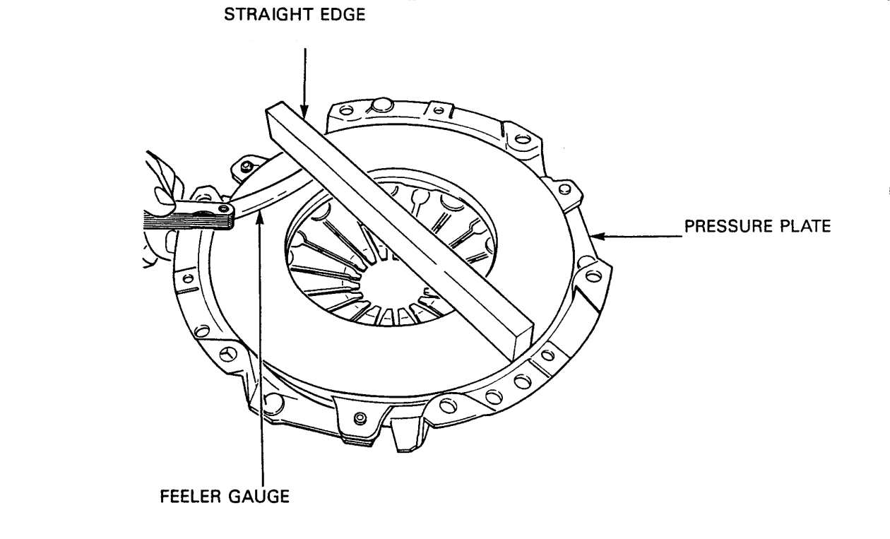
Figure 3-1-1 — Pressure Plate Distortion Check
7.Inspection — To inspect, proceed as follows:
- Check the contact surface of the pressure plate and flywheel for signs of heat, discoloration, cracks and wear.
- Using a straight edge and feeler gauge, inspect the contact surface of the pressure plate for wear and distortion, see Figure 3-1-1. If inward taper or distortion exceeds 0.3 mm, replace the pressure plate.
- Check the pressure plate cover for cracks and ensure the rivets are tight and undamaged. Replace the pressure plate, if necessary.
- Check the diaphragm spring fingers at the location of the throw-out bearing contact for grooving. If grooving exceeds 0.3 mm in depth, replace the pressure plate.
- Check the friction material of the clutch disc for wear. The minimum allowable distance above the rivet heads is 2.0mm.
- Check the disc for run-out; measure 2.5 mm from the outer edge of the disc. The maximum wear limit is 0.5 mm.
- Check the disc for loose or broken rivets, broken springs and for signs of oil and grease. Replace the disc if necessary.
- Inspect the throw-out bearing and pilot bearing for wear and replace if necessary.
8.Installation — To install, proceed as follows:

Figure 3-1-2 — Installation of Clutch Pressure Plate
- Insert the tool 10-213 into the clutch disc and insert into the crankshaft pilot bearing.
- Place the pressure plate against the flywheel, ensuring the dowel pins of the flywheel fit into the centering holes of the pressure plate.
- Install the pressure plate to the flywheel with six socket head screws and torque to 25 N•m (18 ft lb) in a diagonal sequence, see Figure 3-1-2.
- Remove the tool.
- Install the engine (refer to Part 2, Section 6).
Clutch Release Bearing
9.Removal — Replace the clutch release bearing if grinding noises are heard when the clutch pedal is depressed. To remove the release bearing, proceed as follows:
- Remove the engine (refer to Part 2, Section 6).
- Unhook the left and right release bearing springs from the fingers on the shaft.
- Remove the release bearing.
10.Inspection — To inspect, proceed as follows:
NOTE — Do not wash the prepacked bearing.
- Ensure the bearing moves freely, but there is not excessive play in the bearing.
- Replace the bearing if necessary.
11.Installation — To install, proceed as follows:
- Install the bearing over the guide sleeve and hook the springs onto the fingers of the shaft. Ensure the springs are properly hooked behind the fingers.
- Install the engine (refer to Part 2, Section 6).
Clutch Release Bearing Shaft and Seals
12.Removal — To remove, proceed as follows:
- Remove the clutch release bearing.
- Grip under the clutch release shaft spring with brake spring pliers and pry the spring to the right side with a screwdriver.
- Remove the clutch lever.
- Remove the heavy-tension snap ring from the shaft.
- Pry the bushing cap from the shaft.
- Remove the “O” ring.
- Pry the bushing from the shaft.
- Work the shaft all the way out, until the end of the shaft is free of the inner bushing. Push the shaft to the left until the end of the shaft is free of the housing. Remove the shaft.
- Use a small screwdriver to pry out the “O” ring that is inside the housing.
- If the inner bushing is worn, remove the bushing as follows:

Figure 3-1-3 — Removal of Clutch Release Shaft Bushing
- Remove the clutch shaft stop for access to the bushing.
- Insert internal extractor KUKKO 21/3, into the bushing and tighten the nut, see Figure 3-1-3.
- Insert sliding hammer and adapter VW 771/15 through the shaft opening in the housing, and screw it onto the internal extractor.
- Remove the bushing.
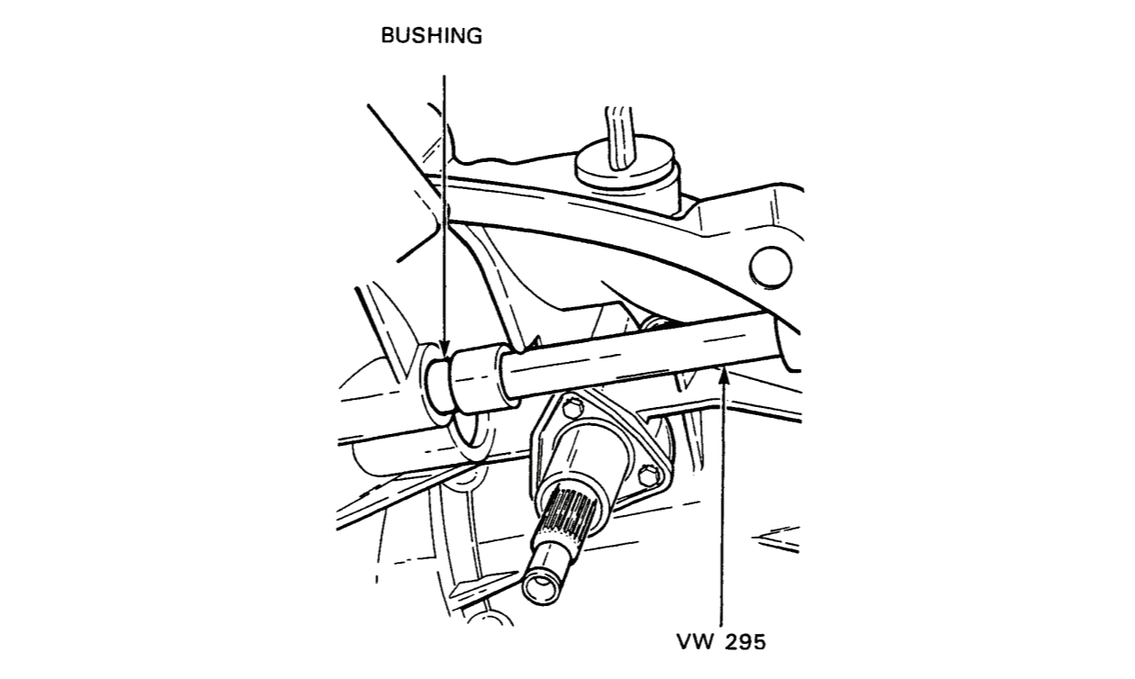
Figure 3-1-4 — Installation of Clutch Release Shaft Bushing
13.Installation — To install, proceed as follows:
- Place the bushing on VW 295 bushing installer.
- Insert the installer through the shaft opening in the housing, see Figure 3-1-4.
- Install the bushing until it bottoms in the hole.
- Install the new lightly lubricated “O” ring in the housing groove.
- Install a new release shaft stop with the foot facing down.
- Install the spring on the shaft with the straight end pointing up and towards the left side of the housing.
- Lubricate the inner bushing.
- Insert the left end of the shaft into the housing and slide it through the bushing hole until the right end of the shaft can be inserted into the inner bushing.
- With the lug on the bushing facing upwards, tap the bushing all the way into the housing, ensuring that the lug fits into the recess.
- Lubricate a new “O” ring, install the “O” ring on the shaft and push it into the recess in the bushing.
- Install the bushing cap. Push on the cap until its outer edge seats on the “O”ring on the bushing.
- Install the snap ring, ensuring it rests flush against the bushing cap.
- Install the clutch lever so that the end of the lever is in line with the lower edge of the boss on the flywheel housing.
- Tap the end of the shaft until one arm of the shaft is in line with the groove on the stop.
- Tap the arms down as far as they will go.
- Using brake spring pliers and a screwdriver, hook the end of the spring over the left arm of the shaft.
- Install the clutch release bearing.
Clutch Cable and Casing (Adjustment)
14.Removal — To remove, proceed as follows:
- Unhook the clutch cable from the hook on the end of the pedal arm.
- Unhook the cable from the hook of the clutch lever.
- Remove the cable casing and grommet from the engine mounting bracket and remove the clip from the cable casing and HT cable.
- Pull the cable through the firewall into the engine compartment.
15.Installation and Adjustment — To install, proceed as follows:
- From the engine compartment, push the clutch cable through the hole in the firewall, into the passenger compartment.
- Hook the cable onto the hook of the pedal arm.
- Hook the cable onto the hook of the clutch lever.
- Install the cable casing and grommet into the engine mounting bracket.
- Position the washer against the grommet on the firewall and pull the cable casing to adjust the clutch pedal free play to between 15 and 20 mm (0.6 to 0.8 in). Install the clip in the grooves of the casing.
- Install the plastic clip on the casing and coil HT cable.
Brake Pedal and Clutch Pedal Bushings
16.Removal — To remove, proceed as follows:
- Disconnect the return spring and the yoke of the push rod from the arm of the brake pedal.
- Disconnect the return spring and cable from the arm of the clutch pedal.
- Remove the retaining clip from the brake/clutch pedal shaft.
- Remove the brake pedal from the shaft.
- Remove the shaft from the steering column bracket.
- Remove the clutch pedal from the shaft.
- Using a punch and hammer, drive out the bushing in the arms of the brake pedal and clutch pedal.
17.Installation — To install, proceed as follows:
- Install new rubber pads on the pedals if necessary.
- Using a vise, press a new bushing into the arms of the brake pedal and clutch pedal.
- Insert the clutch/brake pedal shaft through the bushing in the arm of the clutch pedal and then insert the shaft through the steering column bracket.
- Install the brake pedal on the shaft.
- Install the retaining clip on the end of the shaft.
- Connect the yoke of the brake push rod and return spring to the arm of the brake pedal.
- Hook the clutch cable to the arm of the pedal and connect the return spring to the arm of the clutch pedal.
Transaxle
18.Removal — To remove, proceed as follows:
- Remove the power pack (refer to Part 2, Section 7).
- Remove the starter (refer to Part 2, Section 5).
- Remove the two clutch housing cap screws and lock washers from the bottom of the housing.
- Remove the three clutch housing cap screws and lock washers from the top of the housing.
NOTE — The top left clutch housing cap screw also secures the heater hose rod to the housing. Remove the rod after removing the cap screws.
- Remove the clutch housing cap screw that also secures the engine ground strap to the housing.
- Remove the clutch housing bolt, nut and washer from the right side of the housing.
- Pull the transaxle away from the engine.
- Remove the clutch housing gasket and clean the inside surface of the housing.
19.Installation — To install, proceed as follows:
- Install a new gasket on the clutch housing.
- Position the engine and transaxle so that their flanges are parallel and slide the transaxle towards the engine until the splines of the input shaft contact the splines of the clutch disc.
- Turn the crankshaft until the splines on the transaxle input shaft mesh with the splines of the clutch disc and push the transaxle towards the engine until the clutch housing gasket contacts the engine block.
- Install the three clutch housing cap screws and lock washers at the top of the housing but do not tighten.
NOTE — The top left clutch housing securing cap screw also secures the heater hose securing rod to the housing.
- Install the clutch housing bolt, washer and nut on the right side of the housing.
- Install the engine ground strap to the clutch housing with a cap screw and lock washer.
- Install the two clutch housing cap screws and lock washers to the bottom of the housing and torque to 25 N•m (18 ft lb).
- Torque the four clutch housing cap screws at the top and left of the housing and the housing bolt to 55 N•m (41 ft lb).
- Install the starter (refer to Part 2, Section 5).
- Install the power pack (refer to Part 2, Section 7).
20.Removal — To remove, proceed as follows:
- Remove the engine (refer to Part 2, Section 6).
- Remove the clutch release bearing.
- Remove the locking collar and guide sleeve by removing the three cap screws.
- Using a small screwdriver, pry the input shaft oil seal from the clutch housing, being careful not to scratch the input shaft sealing surface.
21.Cleaning and Inspection — To clean and inspect, proceed as follows:
- Clean the shaft and sealing area.
- Inspect the input shaft for damage. If there is damage, a transaxle overhaul will be necessary.
22.Installation — To install, proceed as follows:

Figure 3-1-5 — Installation of Input Shaft Oil Seal
- Lubricate the seal with grease.
- Install a protective sleeve over the splines to avoid damage to the seal.
- Slide the seal over the sleeve, lip side first, and start it squarely into the housing.
- Remove the protective sleeve from the splines.
- Position seal installer VW 454 and Matra 30-100, against the seal and drive it into the housing, see Figure 3-1-5.
NOTE — Do not grease the guide sleeve.
- Install the guide sleeve and locking collar with the three cap screws and torque to 15 N•m (11 ft lb).
- Install the clutch release bearing.
- Install the engine (refer to Part 2, Section 6).
Front Differential Seals (Right Side)
23.Removal — To remove the front differential seals, right side, proceed as follows:
- Remove the drive axle (refer to Section 4).
- Engage two-wheel drive.
- Remove the outer dust cap.
- Mark the two-wheel drive lever and shaft for reinstallation.
- e. Loosen the securing bolt.
- Remove the lever from the shaft.
- Remove the cap screw that retains the flange in the differential. Cut away rubber from centre of dust cap to make access to cap screw that retains the flange to the differential.
- Remove the washer from the flange housing.
- Remove skid plate from engine. Remove two engine mount bolts.
- Disconnect battery.
- Remove six nuts from exhaust manifold.
- Remove bolt from first exhaust hangar.
- Jack up engine.
- Lower exhaust to make clearance so you can proceed.
- Install two cap screws into the holes in the drive flange and remove the flange from housing.

Figure 3-1-6 — Removal of Front Differential Seals - Right Side
NOTE — If the shims come out with the flange and the shaft, reinsert the shims before continuing the procedure or ensure they are in position before reinstalling the shaft.
- Remove the half shaft and the gear from the flange, if the shaft is removed with the flange.
- Inspect the spline of the shaft and replace if necessary.
24.Installation — To install, proceed as follows:

Figure 3-1-7 — Installation of Front Differential Seals - Right Side
NOTE — The inner seal has only one lip and the outer seal has multiple lips.
- Lubricate the lips of the inner seal with grease.
- Install the seal with the lip and spring facing inward.
- Using seal installer Matra 3025, end “A”, and a plastic hammer, drive the seal in, see Figure 3-1-7.
- Lubricate the lips of the outer seal with grease.
- Install the outer seal with the lip and spring facing inward.
- Using a plastic hammer and seal installer Matra 3025, end “B”, drive the seal in.
- Ensure all shims are installed in the carrier shaft.
- Ensure the spacer is on the differential carrier shaft.
- Hold up the sliding collar.
- Install the half shaft and gear in the sliding collar.
- Turn the half shaft and gear until it fits into the sliding collar and the splines on the shaft engage in the carrier shaft.
NOTE — If the needle bearing comes off during shaft removal, install the bearing on the shaft.
- Install the flange by lightly turning it until the teeth engage. When the teeth engage, push the flange fully in.
- Install the washer in and over the small dowel on the flange and tap it into place.
- Install the cap screw and torque to 25 N•m (18 ft lb).
- Install the dust cap.
- Align the scribe marks of the twowheel drive lever and shaft. Install the lever and tighten the bolt.
- Install the linkage on the lever.
- Install the drive axle (refer to Section 4).
Front Differential Seal (Left Side)
25.Removal — To remove, proceed as follows:
- Remove the drive axle (refer to Section 4).
- Remove the cap screw that retains the flange in the differential.
- Install two cap screws into the holes inthe drive flange and remove the flange from the housing.
NOTE — If the shims come out with the flange and shaft, reinsert the shims before continuing the procedure or ensure they are in position before reinstalling the shaft.
26.Inspection — Inspect the splines of the shaft and replace, if necessary.
27.Installation — To install, proceed as follows:

Figure 3-1-8 — Installation of Front Differential Seal - Left Side
- Lubricate the lip of the seal and place the seal in the housing ensuring the lip faces in.
- Using seal installer Matra 3024, end “A”, drive the seal in. Ensure the outer face of the seal is 9 to 9.5 mm inside the housing, see Figure 3-1-8.
- Install the flange by turning it until the splines engage and push it fully in.
- Install the cap screw and torque to 25 N•m (18 ft lb).
- Install the drive axle (refer to Section 4).
Propeller Shaft Drive Flange Seals
28.Removal — To remove the propeller shaft drive flange seals, proceed as follows:

Figure 3-1-9 — Removal of Propeller Shaft Drive Flange Securing Nut
- Remove the six socket head cap screws and three tab locks from the propeller shaft front constant velocity joint and lower the propeller shaft.
- Remove the cap from the inside of the flange.
- Using a punch and hammer, unlock the flange nut collar from the groove in the shaft.
- Install three cap screws and Matra 3028 tool on the drive flange, see Figure 3-1-9.
- Using a 36 mm socket, remove the flange nut.
NOTE — If the front wheels of the vehicle are resting on the ground, and the transmission is in gear and hand brake applied, it is not necessary to use the Matra 3028 tool as the shaft will not turn under these conditions. The tool is necessary if the procedure is done on a work bench.
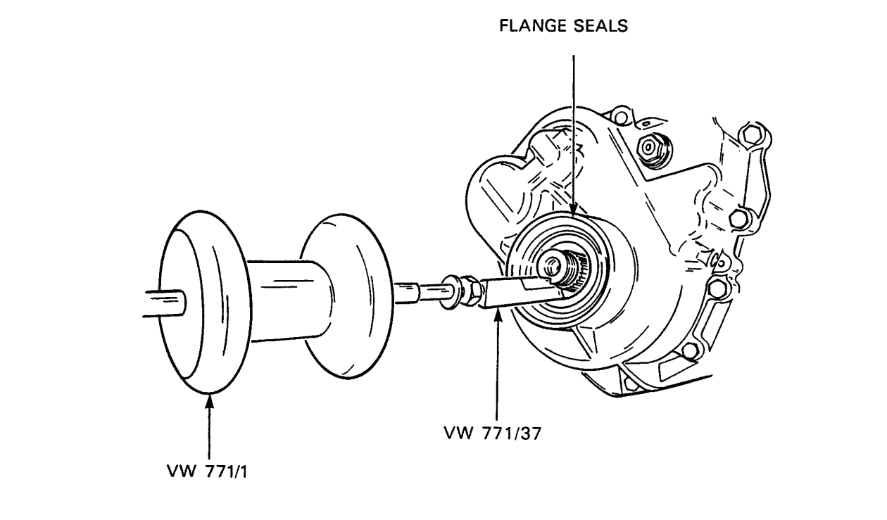
Figure 3-1-10 — Removal of Propeller Shaft Drive Flange Seals
- Remove the flange.
- Remove the flange gasket from either the flange or the propeller shaft.
- Using seal puller VW 771/37 on the end of sliding hammer VW 771/1, remove the outer and inner seals, see Figure 3-1-10.
29.Installation — To install the propeller shaft drive flange seals, proceed as follows:
- Inspect the seal mating surface for gouges and grooves and repair, if necessary.
- Lubricate the lip of the inner seal.
NOTE — The inner seal has only one lip and the outer seal has multiple lips.

Figure 3-1-11 — Installation of Propeller Shaft Drive Flange Seals
- Using end “A” of installer Matra 3026, install the inner seal with the spring facing inward, over the shaft and into the housing, see Figure 3-1-11.
- Using a plastic hammer and seal installing tool, drive the seal in.
- Lubricate the lips of the outer seal.
- Install the seal with the spring facing inwards.
- Using a plastic hammer and the seal installing tool, end “B”, drive the seal in.
- Install the flange on the shaft, ensuring the splines are aligned.
- Install the nut.
- If necessary, install tool Matra 3028, to prevent the flange from turning.
- Torque the flange nut to 150 N•m (111 ft lb).
- Peen the collar on the flange nut into the groove in the shaft.
- Install the cap.
- Install the gasket with the adhesive side towards the flange.
- Install the constant velocity joint of the propeller shaft against the flange and install the six cap screws and three tab locks.
- Torque the cap screws to 45 N•m (28 ft lb).
Two-wheel Drive Lever
30.Removal — To remove, proceed as follows:
- Disconnect the linkage from the lever.
- Scribe match marks on the lever and shaft if the lever is to be used again.
- Loosen the drive lever bolt.
- Remove the lever from the shaft.

Figure 3-1-12 — Adjustment of Two Wheel Drive Lever
31.Installation — If the lever was marked with scribe marks during removal, place the lever on the shaft, ensuring the scribe marks are aligned. Install the bolt and secure the linkage to the lever. The following adjustment procedure applies to the installation of a new or unmarked two-wheel drive lever. To adjust, see Figure 3-1-12 and proceed as follows:
- Move the interlock lever fully forward.
- Move the two-wheel drive lever fully forward.
- Measure the distance between the centre points on the levers. The distance should be 102 mm.
- If the distance between the centre points is not 102 mm, reposition the two-wheel drive lever on the splines until the measurement is correct.
- When the drive lever is in the correct position, install the bolt and washers. Secure with an elastic nut.
Speedometer Drive Gear
32.Removal — To remove, proceed as follows:
- Remove the speedometer cable from the transaxle housing coupling.
- Remove the coupling from the housing.
- Remove the speedometer driven gear.
- Remove the left drive flange.
- Remove the flange seals.
- Remove the speedometer drive gear from the differential carrier.
33.Inspection — To inspect, proceed as follows:
- Inspect the teeth of the speedometer driven and drive gears. Replace the gears if the teeth are damaged.
- Ensure the square at the top of the speedometer driven gear is undamaged. Replace, if damaged.
34.Installation — To install, proceed as follows:
- Lubricate the inside of the speedometer coupling.
- Install the drive gear on the carrier, ensuring the lugs on the gear engage the slots of the carrier.
- Install new flange seals.
- Install the drive flange.
- Insert the driven gear, ensuring the teeth engage the teeth on the drive gear.
CAUTION — To prevent damage to the coupling, do not over tighten. The coupling is made of aluminium.
- Install the coupling in the housing, longest end first over the driven gear, and tighten.
- Install the speedometer cable.
Gear Shift Lever and Tower
35.Removal — To remove, proceed as follows:
- Ensure the transmission is in neutral.
- Remove the eight nuts from the gear shift lever tower boot and remove the seal plate.
- Lift up the boot on the shaft and raise the collar off the transmission.
- Loosen the clamp for the tower breather hose and pull the hose and clamp away from the breather tube.
- Remove the four socket head cap screws from the tower.
- Remove the gear shift lever and tower from the transmission.
- Remove the spring, spring seat and shift tower gasket from the transmission and cap the transmission opening.

Figure 3-1-13 — Neutral Alignment of Shifter Rods

Figure 3-1-14 — Spring and Selector Finger of Transmission Shift Lever

Figure 3-1-15 — Adjustment of Clearance Between Gear Shift Lever Stop and Shift Tower Stop
36.Installation — To install, proceed as follows:
- Remove the cap from the transmission opening for the gear shift lever and place a new gasket on the transmission opening.
- Ensure that the transmission is in neutral by aligning the three shifter rods, see Figure 3-1-13.
- Insert the end of the spring into the hole in the selector finger and install the spring seat on the base of the selector spring, see Figure 3-1-14.
- Insert the selector finger of the gear shift lever into the transmission opening ensuring the breather tube of the tower faces toward the front of the vehicle and the selector finger enters the slot in the transmission selector rod.
- Install the four socket head cap screws (apply a sealing compound to the left front securing screw), and torque all four screws to 25 N•m (18 ft lb).
- To adjust the gear shift lever position, proceed as follows:
- Ensure that the gear shift lever is in neutral and fully to the right in the third and fourth gear shift gate.
- Measure the clearance between the gear shift lever stop and the gear shift tower stop, see Figure 3-1-15.
- If the clearance is not 9 mm, loosen the nut and rotate the shift lever to obtain the correct clearance.
- Torque the nut to 45 N•m (33 ft lb) and recheck the clearance.
- Install the tower breather hose on the breather tube.
- Lower the collar and boot onto the tower.
- Install the seal plate and secure with the eight self-locking nuts.
Section 2 — Propeller Shaft and Propeller Shaft Constant Velocity Joints
General
Propeller Shaft Description
1.The propeller shaft is located between the transaxle and rear differential. There is a constant velocity joint at each end of the shaft.
Propeller Shaft Operation
2.The propeller shaft transmits driving torque from the transaxle to the rear differential.
Component Removal and Installation
WARNING — Do not replace metric bolts with standard bolts. See the WARNING page at the front of the manual.
Propeller Shaft
3.Removal — To remove, proceed as follows:
- Remove the six socket head cap screws and three tab locks from the front constant velocity joint and lower the front end of the shaft.
- Remove the six socket head cap screws and three tab locks from the rear constant velocity joint and remove the propeller shaft.
4.Inspection — Inspect the propeller shaft for distortion and replace, if necessary.
5.Installation — To install, proceed as follows:
- Install a new gasket with the adhesive side on the transaxle output flange. Position the front constant velocity joint against the flange and install three tab locks and the six socket head cap screws. Loctite 242 must be applied to the threads. Torque the cap screws to 45 N•m (33 ft lb).
- Install a new gasket with the adhesive side on the differential input flange. Position the rear constant velocity joint against the flange and install the three tab locks and six socket head cap screws. Loctite 242 must be applied to the threads. Torque the cap screws to 45 N•m (33 ft lb).
Propeller Shaft Constant Velocity Joints
6.The removal, disassembly, cleaning and inspection, assembly and installation procedures are the same for both constant velocity joints.
7.Removal — To remove, proceed as follows:
NOTE — Mark the position of the CV joint on the shaft before removing. Otherwise the shaft may require rebalancing.
- Remove the propeller shaft.
- Stand the shaft on end and clamp it in a vise but do not distort the shaft.
- Remove the circlip from the end of the propeller shaft.
- Loosen and remove the small boot clamp.
- Slide the dust boot toward the CV joint and out of the recessed groove on the propeller shaft.
- Using a puller, remove the CV joint from the shaft, ensuring the boot comes with the joint.
- Clean the end of the shaft and inspect the splines for wear and damage. Replace the shaft, if necessary.
- Remove the shaft from the vise.
8.Disassembly — To disassemble, proceed as follows:
- Tilt the hub and cage in the outer ring to expose a ball bearing and press the bearing out of the cage.
- Repeat step a. until all six balls have been removed.
- Remove the hub and cage from the outer ring.
- Turn the hub in the cage and remove the hub from the cage.
- Remove grease from all CV joint components.
- Clamp the outer ring in a vise.
- Using a punch, remove the protective cap from the outer ring.
9.Cleaning and Inspection — To clean and inspect, proceed as follows:
- Inspect the boot of the protective cap for wear and damage. The boot is part of the cap. If the boot is damaged or worn, replace the cap.
- Clean all components of the CV joint.
- Inspect bearing surfaces for scoring.
- Measure the diameter of the balls. Each ball should be 19 mm in diameter.
- Measure each ball at several points to check roundness.
- Check the outer ring for scoring. It is not necessary to replace the outer ring, if ball-track marks are present.
10.Assembly — To assemble, proceed as follows:

Figure 3-2-1 — Alignment of Hub and Outer Ring
- Press 45 grams of VW G-6 grease into the outer ring.
- Install the hub in the cage, ensuring the inner bevelled edge of the cage is at the top and the boss end of the hub is at the bottom.
- Install the cage in the outer ring, ensuring the large flats of the hub are aligned with the small flats of the outer ring, see Figure 3-2-1.
- Tilt the hub in the cage and insert a ball.
- Tilt the hub to expose the hub side that is opposite the side with the ball and insert a ball.
- Repeat steps d. and e. until all six balls have been installed. Ensure the large flats of the hub remain aligned with the small flats of the outer ring.
- Press 45 grams of VW G-6 grease into the CV joint.
- Ensure the joint moves freely over the complete range of axial movements.
11.Installation — To install, proceed as follows:
- Install the dust boot clamp.
- Lightly grease the inside of the dust boot and grease the splines of the shaft.
NOTE — Ensure the aligning marks are matched.

Figure 3-2-2 — Installation of Propeller Shaft Constant Velocity Joint
- Push the protective cap as far as possible onto the end of the shaft.
- Tap the CV joint onto the end of the shaft, see Figure 3-2-2.
- Install a new circlip on the end of the shaft.
- Using socket head cap screws, align the protective cap with the outer ring and tap the cap onto the outer ring.
- Ensure the dust boot is seated in the recessed groove on the shaft.
- Crimp the dust boot clamp.
- Install the propeller shaft.
Section 3 — Rear Differential
General
Rear Differential Description
1.The rear differential has the same internal construction as the front differential, but also has a differential lock capability to prevent slippage of one wheel independent of the other. Drive from the rear differential to the rear wheels is through drive axles.
Rear Differential Operation
2.The rear differential receives driving torque from the propeller shaft through the input flange. The input flange drives the pinion gear, which in turn drives the crown gear. The crown gear, which is bolted to the differential carrier, rotates and carries the pinion and side gear with it. Drive and differential action are transmitted to both rear drive axles. When the differential lock is engaged, a sliding sleeve in the left differential flange housing locks the drive flange to the differential carrier. Locking the drive flange to the carrier eliminates differential action and both drive axles are driven as a single unit.
Component Removal and Installation
WARNING — Do not replace metric bolts with standard bolts. See the WARNING page at the front of the manual.
Rear Differential
3.Removal — To remove, proceed as follows:
- Remove the drain plug to drain lubricant from the rear differential. (This step is required if the differential is being returned to supply.)
- Remove the fuel tank protection plate.
- Place axle stands beneath the vehicle frame, at points immediately behind the body mounting bolts nearest the rear hub assemblies, and remove the rear wheels.
- Place the transmission in gear and engage the differential lock to prevent the drive axles from turning.
- Remove the rear drive axles.
- Disconnect the rear propeller shaft CV joint and gently lower the shaft.
- Remove the spring clip pin and washer from the differential lock lever and pull the linkage away from the lever.
- Disconnect the two connectors from the differential lock sending unit.
- Remove the differential vent line from the tube located at the bottom of the left rear fender well.
- Remove the two nuts and washers from the fuel pump mounting bracket and move the pump and bracket to the side.
- Position a jack under the centre of the differential.
- Remove the self-locking nut and small flat washer from each of the three mounts.
- Remove the large flat washer and top rubber mount from each mount.
- Raise the differential and remove the three lower rubber mounts and large flat washers from the mounting brackets of the vehicle frame.
- Move the jack and differential forward until the differential mounts are clear of the mounting brackets.
- Lower the differential clear of the vehicle.
4.Installation — To install, proceed as follows:
NOTE — If a new differential is to be installed, disconnect the vent line and remove the differential lock sending unit from the used differential. Install the differential lock sending unit and vent line on the new differential.
NOTE — Prior to installation, check the differential lock lever adjustment, see Figure 3-3-2.
- Position the differential on a jack.
- Position the jack under the vehicle so that the mounts of the differential are below and forward of the mounting brackets on the vehicle frame.
CAUTION — To prevent damage, ensure the differential does not bind with the rear drive axles and the fuel pump when aligning the differential mounts with the mounting brackets.
- Raise the differential until the mounts are above the mounting brackets on the vehicle frame and then slide the jack toward the rear of the vehicle until the mounts are aligned with the corresponding mounting brackets.
- Install a large flat washer and lower rubber mount on each of the three mounting brackets.
- Lower the differential until it rests on the three lower rubber mounts.
- Install a small flat washer on each of the three mounting bolts and then insert a mounting bolt up through each mounting bracket and mount.
- Install a top rubber mount, large flat washer, small flat washer and a new self-locking nut on the mounting bolts.
- Torque the mounting bolts to 40 N•m (30 ft lb).
- Install the two nuts and washers on the fuel pump bracket, ensuring the pump grounding wire is secured to the bracket with one of the nuts.
- Install a new propeller shaft gasket on the differential flange.
- Raise the propeller shaft and install the three tab locks and six socket head cap screws to secure the shaft to the differential.
- Torque the six socket head cap screws to 45 N•m (33 ft lb).
- Install the differential lock lever linkage on the lock lever with a flat washer and spring clip pin.
- Install the drive axles to the differential with the three tab locks and six socket head cap screws and torque to 45 N•m (33 ft lb).
- Connect wires #90E and #28 to the terminals of the differential lock sending unit.
- Install the vent line on the tube.
- Install the drain plug and remove the filler plug.
- Add lubricant until the lubricant is even with the bottom of the fill hole and then install the filler plug.
- Install the rear wheels and remove the two axle stands.
- Torque the wheel mounting bolts to 175 N•m (129 ft lb).
- Install the fuel tank protection plate.
- Disengage the differential lock lever.
Rear Differential Propeller Shaft Drive Flange Seal
5.To remove and install the seal, follow the removal and installation procedures for the transaxle propeller shaft drive flange seals (refer to Section 1). Use seal installer 3027 instead of 3026. Prior to installing the flange nut, remove all grease from the nut and shaft threads. Coat the nut and shaft threads with Loctite #242. Tighten the nut exactly to its original position and lock the collar of the nut. The nut must not be tightened beyond the original position and backed off.
Rear Differential Seal (Right Side)
6.Removal — To remove, proceed as follows:
NOTE — Seals may be replaced with the differential in the vehicle.
- Remove the drive axle (refer to Section 4).
- Engage the differential lock.
- Remove the drive flange retaining bolt.
- Remove the flange from the housing.
7.Installation — To install the differential seal on the right side, follow the installation procedure for the front differential seal (left side) (refer to Section 1).
Rear Differential Seals (Left Side)
8.Removal — To remove, proceed as follows:
- Remove the drive axle (refer to Section 4).
- Engage the differential lock.
- Mark the differential lock lever and shaft for reinstallation before removing the lever.
- Loosen the retaining bolt and nut on the lever.
- Remove the lever from the shaft.
- Remove the drive flange retaining bolt.
- Install two cap screws in the holes in the drive flange and remove the flange from the housing.
- If the differential lock gear comes out with the flange, reinstall the gear in the sliding collar.
NOTE — Ensure all shims are installed first, and install the gear, ensuring the large boss end faces in and the chamfer on the teeth faces out.
9.Installation — To install new inner seals, proceed as follows:

Figure 3-3-1 — Installation of Rear Differential Seal - Left Side
- Lubricate the lips of the inner seal with grease.
- Install the seal with the lip and spring facing inward.
- Using end “A” of Matra 3025, install the inner seal, see Figure 3-3-1, and, using a plastic hammer, drive the seal in.
- Lubricate the outer seal lips with grease.
- Install the seal with the lip and spring facing inward.
- Use end “B” of Matra 3025 and a plastic hammer and drive the seal in.
- Ensure all shims that belong on the end of the shaft are in place.
NOTE — It may be necessary to rotate, or disengage the differential lock lever to fully seat the flange.
- Install the flange and shaft in the housing, ensuring they are pushed fully in.
- Install the retaining bolt.
- Engage the differential lock.
- Torque the retaining bolt to 25 N•m (18 ft lb).
- Install the differential lock lever on the shaft. Ensure the match marks are aligned.
- If match marks were not made, adjust the lever as follows:
- Rotate the shaft to the centre detent.
- Rotate the drive flange so that two of the bolt holes and the top differential flange retaining bolt are in a straight line.

Figure 3-3-2 — Adjustment of Rear Differential Lock Lever
- Place a ruler along the vertical line made by the two bolt holes and the flange retaining bolt, and measure the distance from the vertical line to a centre line on the lever, see Figure 3-3-2. The distance from the centre line on the lever to the straight edge of the ruler should be 25 mm. Rotate the lever on the splines in the required direction until the correct measurement is obtained. Secure the lever retaining nut and bolt.
- Install the drive axle (refer to Section 4).
Section 4 — Drive Axles and Wheel Hub Assemblies
General
Description of Drive Axles
1.There are four drive axles. Each drive axle has an inner and outer constant velocity joint (paragraph 5 and paragraph 10), see Figure 3-4-1.
Operation of Drive Axles
2.The drive axles transmit driving torque from the differentials to the wheel hubs.
 | 1. | Outer constant velocity joint |
| 2. | Circlip | |
| 3. | Large retaining clamp | |
| 4. | Outer dust boot | |
| 5. | Small retaining clamp | |
| 6. | Drive axle | |
| 7. | Inner dust boot | |
| 8. | Large retaining clamp | |
| 9. | Protective cap | |
| 10. | Inner constant velocity joint | |
| 11. | Circlip |
Figure 3-4-1 — Drive Axle
Component Removal and Installaton
WARNING — Do not replace metric bolts with standard bolts. See the WARNING page at the front of the manual.
Drive Axles
3.Removal — To remove, proceed as follows:
- Remove the drive axle nut.
- Support the vehicle with an axle stand and remove the wheel.
- Remove the six socket head cap screws and three tab locks from the inner CV joint.
- Remove the rubber brake line at the bracket on the steering arm.
- Remove the cotter pin and castellated nut. Using tie-rod puller Snap-On GA 390, remove the tie-rod end from the steering arm. Install the tool under the rubber dust boot to avoid damaging the boot.
- Place a jack under the ball joint and raise the hub assembly so that the jack supports the weight of the assembly.
- Remove the mounting bolt and selflocking nut that secure the spring assembly to the spring trunnion.
- Lower the hub assembly.
NOTE — On the rear hub assemblies, ensure the weight of the hub is supported, so it is not on the hand brake cable.
- Tilt the hub assembly away from the vehicle.
- Remove the drive axle assembly.
- If the “O” ring remains with the outer CV joint, remove it.
4.Installation — To install, proceed as follows:
- Place the stub axle in the wheel hub ensuring the “O” ring is in place. Place the inner CV joint against the drive flange and install the three tab locks and six socket head cap screws. Loctite 242 must be applied to the threads. Torque the cap screws to 45 N•m (33 ft lb).
- Raise the jack and install the spring mounting bolt through the spring trunnion and the spring bushing. Install a new self-locking nut and torque to 90 N•m (66 ft lb).
NOTE — Ensure the round shoulders of the trunnion face inward.
- Lower the hub assembly and remove the jack.
- Install the tie-rod end into the steering arm. Install a castellated nut and torque to 40 N•m (30 ft lb).
- Install a cotter pin.
- Connect the rubber brake line at the bracket on the steering arm.
- Install the wheel.
- Remove the axle stand.
- Install the drive axle nut onto the stub axle and torque to 100 N•m (74 ft lb).
- Torque the wheel mounting bolts to 175 N•m (129 ft lb).
Drive Axle Inner Constant Velocity Joints
5.Removal — To remove the inner CV joint from a drive axle, see Figure 3-4-1 and proceed as follows:

Figure 3-4-2 — Removal of Inner Constant Velocity Joint from Drive Axle
- Remove the drive axle.
- Remove the two boot retaining clamps (5 and 8) and slide the boot (7) away from the protective cap (9).
- Remove the circlip (11) from the end of the axle (6).
- Place tool VW 522 on the axle and against the hub of the CV joint, see Figure 3-4-2.
- Press the CV joint (10) from the axle.
- Pull the boot (7) from the axle.
6.Disassembly — To disassemble, proceed as follows:

Figure 3-4-3 — Removal of Ball from Inner Constant Velocity Joint
- Tilt the hub and cage in the outer ring to expose a ball, see Figure 3-4-3.
- Press the ball out of the cage.
- Repeat steps a. and b. until all six balls are removed.
CAUTION — Do not interchange CV joint components as the components of each CV joint are matched to one another.
- Remove the hub and cage from the outer ring.
- Install the outer ring in a soft-jawed vise and, using a punch and hammer, remove the cap from the outer ring.
- Clean and dry all components of the CV joint.
7.Inspection — To inspect, proceed as follows:
- Inspect the inside surface of the outer ring for pitting and discoloration and replace the CV joint if damaged. Do not replace the outer ring if the inside surface has a polished appearance or the ball-track can be seen.
- Inspect the hub and cage for damage, excessive wear and discoloration. Replace the CV joint, if necessary.
- Inspect the balls for pitting, discoloration, roundness and size. The balls of the inner CV joint are 17 mm. Do not interchange balls from one joint with another. If a ball is damaged, replace the CV joint.
- Inspect the drive axle dust boots for tears and replace, if necessary.
- Inspect the axle for damage and straightness.
8.Assembly — To assemble, proceed as follows:
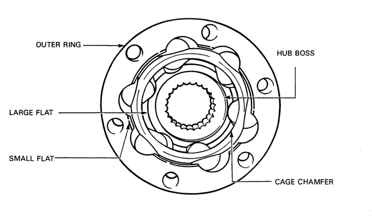
Figure 3-4-4 — Inner Constant Velocity Joint
- Install the hub in the cage, ensuring the boss on the hub and the chamfer on the cage face up, see Figure 3-4-4.
- Lightly lubricate the inside of the outer ring with VW G-6 grease. Place the hub and cage in the outer ring, ensuring a large flat on the hub is in line with a small flat on the ring.
- Press the six balls into the cage one at a time.
- Position the cap on the bottom of the outer ring and insert two socket head cap screws into the bolt holes of the cap and outer ring to ensure the holes are aligned.
NOTE — The bottom of the outer ring is the end without the groove.
- Using a fibre hammer, tap the cap onto the outer ring and remove the socket head cap screws.
- Swivel the hub by hand to ensure it will move over the full range of axial movements.
9.Installation — To install, see Figure 3-4-1 and proceed as follows:
- Place a small clamp (5) on the axle (6).
- Install the inner dust boot (7) on the drive axle and move the boot to the other end of the axle.
- Install the axle in a soft-jawed vise and position the CV joint (10) on top of the axle, ensuring the spline of the axle and CV joint hub are correctly positioned so that the hub and spline will mesh when the CV joint is tapped onto the axle.

Figure 3-4-5 — Installation of Inner Constant Velocity Joint on Drive Axle
- Position tool VW 522 on the end of the hub and tap or press the CV joint onto the axle, see Figure 3-4-5.
- Install a new circlip (11) on the axle above the hub, see Figure 3-4-1.
- Press approximately 45 grams of VW G-6 grease into the joint from the boot side.
- Pull the boot over the collar of the protective cap (9) and install the large boot clamp (8). Ensure the boot remains tight against the collar of the cap after the clamp is installed. Crimp the clamp.
- Fit the clamping surface of the small end of the boot into the groove of the axle. Install the boot clamp (5) and crimp.
- Press another 45 grams of VW G-6 grease into the CV joint.
- Install the drive axle.
Drive Axle Outer Constant Velocity Joints
10.Removal — To remove, see Figure 3-4-1 and proceed as follows:
- Remove the drive axle.
- If the “O” ring remains with the outer CV joint, remove it.
- Remove the two boot retaining clamps (3 and 5) and slide the boot (4) down the axle (6).
- Remove excess grease from the CV joint.
- Place the axle horizontally in a softjawed vise.
- Spread the circlip (2), located on the hub, and tap the CV joint with a fibrehead hammer until the splines of the axle begin to pass the circlip.
- Release the circlip and tap the CV joint from the axle.
11.Disassembly — To disassemble, proceed as follows:
- Tilt the hub and cage to expose a ball and press the ball out of the cage and housing.
- Tilt the hub and cage until the ball on the opposite side to the first ball is exposed and press the ball out of the cage and housing.
- Repeat steps a. and b. until all six balls are removed from the cage and housing.
CAUTION — Do not interchange CV joint components as the components of each CV joint are matched to one another.
- Rotate the hub and cage so that two of the rectangular holes are vertical and in line with the flats of the housing and lift the hub and cage from the housing, see Figure 3-4-6.

Figure 3-4-6 — Removal of Hub and Cage from Housing
NOTE — All of the holes in the cage of some CV joints may be rectangular.
- To remove the hub from the cage, rotate the hub in the cage so that the hub is at right angles to the cage, partially insert one of the lugs of the hub into one of the rectangular holes of the cage and lift the hub out of the top of the cage.
- Remove the circlip from the hub.
- Clean all components of the CV joint.
12.Inspection — To inspect, proceed as follows:
- Inspect the inside surface of the housing for pitting and discoloration and replace if necessary. Do not replace the housing if the inside surface has a polished appearance or the ball-track can be seen.
- Inspect the hub and cage for damage, excessive wear and discoloration. Replace the CV joint, if necessary.

Figure 3-4-7 — Measurement of Stub Axle Distortion
- Inspect the balls for pitting, discoloration, roundness and size. The balls of the outer CV joint are 19 mm (0.750 in). Do not interchange balls from one joint to another. If a ball is damaged, replace the CV joint.
- Inspect the drive axle boot for tears and replace if necessary.
- Using a vernier caliper and machinist's square, measure the stub axle for distortion, see Figure 3-4-7. Make at least three measurements. The difference between any two measurements must not exceed 0.25 mm (0.010 in). Replace the stub axle if necessary.
13.Assembly — To assemble, proceed as follows:
- Press 45 grams of Shell CG 1237 (
9150-21-904-0640) grease into the housing. - Install the hub in the cage by inserting one of the lugs into a rectangular hole. The top of the hub has the circlip ring and the bottom flange of the cage is wider than the top.
- Rotate the hub and cage so that the rectangular holes are at the sides and place the hub and cage in the housing, ensuring the top of the hub and cage face up.
- Tilt the hub and cage to expose one of the rectangular holes of the cage and press a ball into the cage.
- Tilt the hub and cage to expose the rectangular hole on the opposite side to the first ball and press a ball into the hole.
- Repeat steps d. and e. until all six balls are installed.
- Install a new circlip on the end of the hub.
- Press 45 grams of VW G-6 grease into the joint.
- Swivel the hub by hand to ensure the hub will move over the full range of axial movements.
14.Installation — To install, see Figure 3-4-1 and proceed as follows:
- Install a small clamp (5) and the outer dust boot (4) on the drive axle (6) and slide the clamp and boot to the other end of the axle.
- Position the stub axle (1) in a softjawed vise with the open end of the CV joint facing up.
- Using a ball-peen hammer, tap the axle into the hub until the circlip (2) lodges in the groove on the axle.
- Fit the large end of the boot over the end of the CV joint and install the boot retaining clamp (3). Crimp the clamp.
- Slide the clamping surface on the small end of the boot onto the groove on the axle and install the boot retaining clamp (5). Crimp the clamp.
- Install a new rubber “O” ring on the stub axle housing.
- Install the drive axle.
Hub Assemblies
15.Removal — To remove, proceed as follows:
- Support the vehicle on axle stands and remove the wheel.
- Disconnect the rubber brake line at the bracket on the steering arm.
- Remove the brake drum (refer to Part 4, Section 2).
NOTE — For rear hub assemblies, the hand brake cable must be disconnected from the backing plate.
- Remove the tie-rod end from the steering arm.
- Remove the spring retaining nut and bolt from the spring trunnion.
- Remove the drive axle.
- Support the hub assembly and remove the mounting bolts that secure the wishbone arms and shock absorber to the ball joint. Remove the hub assembly.
16.Disassembly — To disassemble, proceed as follows:
- Remove the brake shoes.
- Remove the interconnecting brake line (front hubs only) from both brake cylinders and the brake line from the cylinder at rear of backing plate.
- Remove the interconnecting brake line from the retaining clip on the backing plate.
- Remove the rubber protector cap from the bleeder valve and remove the bleeder valve (rear only).
- Remove the two socket head screws from the steering arm stop, and remove the steering arm stop (front hubs only).
- Remove the three cylinder cap screws and washers (front hubs only) and remove each cylinder from the backing plate.
- Remove the two socket head retaining screws and lock washers from the drive axle dust boot guard at the hub carrier.
- Remove the nut from the ball joint.
WARNING — To prevent injury, stand to the side of the ball joint when closing the jaws of the ball joint remover. There may be a build-up in pressure before the ball joint releases from the hub carrier causing the ball joint to fly off the hub carrier with considerable force.

Figure 3-4-8 — Removal of Ball Joint from Hub Carrier
- Using remover VW 267A, remove the ball joint from the hub carrier, see Figure 3-4-8.
- A new ball joint must be installed during rebuild.
- Remove the steering arm from the hub carrier by removing the three socket head screws.
- Using a fibre-head hammer, tap the steering arm free of the hub carrier and remove the trunnion cup from the carrier housing. A new cup must be installed during assembly.
- Disassemble and assemble the steering arm:

Figure 3-4-9 — Removal of Spring Clip from Trunnion

Figure 3-4-10 — Removal of Steering Arm Bushings
- Remove the “O” ring from the spring trunnion.
- Using a soft-jawed vise, press together the steering arm and spring trunnion so that more of the end of the trunnion pivot is exposed and pry the spring clip from the arm, see Figure 3-4-9.
- Clamp the spring trunnion in the vise with the steering arm uppermost and pull the steering arm from the trunnion.
- Clean and inspect the trunnion pivot. If the pivot wearing surface is pitted, scored or measures less than 29.80 mm on the large diameter, or less than 24.97 mm on the small diameter, replace the pivot.
- Remove the steering arm dust boot.
- Slide the felt ring from the trunnion pivot.
- Clean the inside surface of the bushing housing and inspect the housing for damage. Replace the steering arm if necessary.
- Clamp the steering arm in the vise with the top of the arm facing up.
- Apply a light coat of grease to the inside surface of the bushing housing.
NOTE — The lower bushing has a lip.

Figure 3-4-11 — Installation of Steering Arm Upper Bushing

Figure 3-4-12 — Compressed Trunnion and Steering Arm
- Using tool VW 548, press a new upper bushing into the housing until the top of the bushing is flush with the housing, see Figure 3-4-11.
- Reposition the arm and press in the lower bushing.
- Position a new dust boot on top of the housing with a spring clip.
- Slide a new felt washer onto the trunnion pivot arm and then apply a light coat of grease to the pivot.
- Clamp the spring trunnion into a soft-jawed vise with the pivot on top and slide the steering arm onto the trunnion pivot until the steering arm contacts the felt washer of the spring trunnion.
- Using a soft-jawed vise, press together the steering arm and spring trunnion to expose more of the end of the trunnion pivot and install a spring clip in the groove of the arm, see Figure 3-4-12.
- Remove the spring trunnion and steering arm from the vise and slide a new “O” ring onto the end of the trunnion pivot.
- Ensure the steering arm will turn but does so stiffly.
- Remove the two rubber plugs from the brake shoe inspection holes in the brake backing plate.
- Install the two wheel mounting bolts, opposite each other, into the wheel hub and clamp the bolts into a softjawed vise.

Figure 3-4-13 — Removal of Hub Nut
- Using a ball-peen hammer and punch, tap the sleeve of the hub nut locking collar from the two places in the wheel hub groove where the sleeve is peened into the groove.
- Position hub nut tool PEISELER 2089 on the hub nut and remove the hub nut, see Figure 3-4-13.
NOTE — Considerable force is required to loosen the hub nut, which was torqued to 400 N•m (290 ft lb) during installation.
- Inspect the sealing surfaces of the hub nut for scoring and replace if necessary.

Figure 3-4-14 — Removal of Wheel Hub from Hub Assembly
- Remove the two wheel mounting bolts and insert the fingers of jig 2090 through the holes in the wheel hub until the fingers of the jig contact the hub carrier, see Figure 3-4-14. Remove any of the 6 mm socket head screws that prevent the fingers of the jig from contacting the hub carrier.
- Turn the hub assembly over so that the assembly sits on the jig and place tool 32-108 on the open end of the wheel hub.
- Press the wheel hub from the hub carrier. If a press is not available, tap tool 32-108 with a ball-peen hammer until the wheel hub is free of the carrier.
- Remove the bearing race from the wheel hub:

Figure 3-4-15 — Installation of KUKKO 44-2 and Tool 17-2 on Wheel Hub
- Stand the wheel hub on a flat surface so that the open end of the wheel hub faces up and place puller tool KUKKO 17-2 underneath the bearing race on the wheel hub, see Figure 3-4-15.
- Place tool 40-105 on the open end of the wheel hub and, using Puller 44-2, pull the bearing race from the wheel hub.
- Clean the wheel hub and inspect the wheel hub for scoring and discoloration. Replace the wheel hub if necessary.
- Remove the bearing from the hub carrier:
- Place the hub carrier in a vise with the inside surface of the backing plate facing up and, using a pry bar, remove the outer oil seal.

Figure 3-4-16 — Removal of Bearing or Inner Seal in Hub Carrier
- Using snap ring pliers, remove the outer snap ring from the carrier housing.
- Turn the carrier over and, using a pry bar, remove both seals one at a time from the housing.
- Using snap ring pliers, remove the inner snap ring from the housing.
- Turn the carrier over and place tool Matra 10-550 on top of the bearing. Insert tool Matra 30-505 into tools Matra 10-550 and press or drive the bearing from the housing, see Figure 3-4-16.
- Remove the remaining socket head screws from the backing plate at the hub carrier.
- Scribe match marks on the backing plate and hub carrier to aid reassembly.
- Place the backing plate on supports. Place a block of wood over the hub carrier and tap the wood until the carrier is free of the backing plate.
- Install the bearing and seals in the hub carrier housing:
- Place the hub carrier in a softjawed vise with the outer end of the carrier facing up and install the outer snap ring into the outer groove of the housing.
- Turn the carrier over and apply a light coat of grease to the housing.
- Using tool Matra 10-550 and 30-505, install the bearing into the housing ensuring the bearing contacts the outer snap ring.
- Install the inner snap ring into the inner groove of the housing.
NOTE — The narrow seal goes against the hub nut.
- Coat the lips of the new seals with grease and, using Matra tool 10-550, install the inner seal, ensuring the lip of the seal faces toward the bearing.
- Using tool Matra 10-550 and 30-505, install the outer seal ensuring the lip of the seal faces away from the bearing and the seal is flush with the hub carrier housing.
- Turn the carrier over and, using tool Matra 10-550 and 30-505, install the outer seal, ensuring the lip of the seal faces toward the bearing and the seal is flush with the carrier housing.
17.Assembly — To assemble, proceed as follows:
- Place the carrier in a soft-jawed vise with the outer end facing up.
- Ensure the brake adjusting pins rotate freely in the backing plate and apply a light coat of oil to both adjusting pins.
- Lower the backing plate onto the carrier, ensuring the scribe marks of the plate and carrier are aligned.
NOTE — If installing a new front backing plate, or if scribe marks were not made, install the backing plate to the hub carrier with the brake cylinders at the four and ten o'clock positions for the right hub and at the eight and two o'clock positions for the left hub.
NOTE — If installing a new rear backing plate, install the backing plate to the hub carrier with the brake cylinder position between twelve to one o'clock for the right hub and between eleven to twelve o'clock for the left hub.
NOTE — The top backing plate mounting screw on rear backing plates is left out for wheel cylinder clearance.
- Install the twelve socket head screws and torque to 35 N•m (25 ft lb) in a diagonally opposite sequence.
- Apply a light coating of grease to the outer surface of the wheel hub.

Figure 3-4-17 — Installation of Wheel Hub
- Using tool 415A, press the wheel hub part way into the carrier so that the hub nut can draw the wheel hub all the way into the carrier when the nut is installed, see Figure 3-4-17. Ensure the wheel hub goes in straight.
- Screw two wheel mounting bolts into the wheel hub and clamp the two bolts into a soft-jawed vise.
NOTE — Each hub nut can only be used twice and then must be discarded.
- Apply a light coat of grease to the sealing surfaces of the hub nut.
- Using tool PEISELER 2089, install the nut onto the wheel hub and torque to 400 N•m (290 ft lb).
- Peen at opposite sides the sleeve of the nut locking collar into the groove of the wheel hub. If the nut is being used for the second time, peen the sleeve of the collar at two new locations. Do not peen the sleeve of the collar into the two places where the sleeve was previously peened.
- Place the brake cylinder(s) on the backing plate, ensuring the teeth of the adjuster mesh with the adjuster pinion on the backing plate.
- Loosely install the cylinders to the backing plate with cap screws and washers for each cylinder.
- Insert the interconnecting brake line rubber collar (front hubs only) into the retaining clip on the backing plate and connect the line to both brake cylinders. Connect the brake line to the cylinder at the rear of the backing plate.
- Torque the brake cylinder retaining cap screws to 25 N•m (18 ft lb).
- Install the brake shoes and return springs.
- Screw the bleeder valve into the cylinder and install the rubber protector cap.
- Insert a rubber plug into each brake shoe inspection hole in the backing plate.
- Install the trunnion cup in the carrier housing and apply a light coating of grease to the exposed end of the spring trunnion pivot.
- Insert the trunnion pivot into the recess in the hub carrier. If rebuilding a front hub assembly, the steering arm will point toward the rear of the vehicle when the hub assembly is installed. If rebuilding a rear hub assembly, the steering arm should point toward the front of the vehicle when the hub assembly is installed. A new or rebuilt hub assembly must have a maximum axial play of 1.3 mm at the trunnion pivot.
- Install the steering arm to the hub carrier. Turn the spring trunnion as required to install the socket head screws and torque to 65 N•m (48 ft lb).
- Insert the ball joint into the mount on the hub carrier.
- Install a nut on the ball joint; as the nut is screwed on, pull out on the wishbone connecting arm of the ball joint until the nut is snug and then torque the nut to 100 N•m (74 ft lb). Retorque the nut every 7,500 km, or once a year.
- Ensure the rounded side of the spring trunnion arms are farthest from the backing plate.
- Position the steering arm stop on the hub carrier, ensuring the flat end of the stop is between the backing plate and the steering arm.
- Install two socket head screws and torque to 25 N•m (18 ft lb).
- Place the drive axle dust boot guard on the hub carrier. Install two socket head retaining screws and washers and torque to 25 N•m (18 ft lb).
18.Installation — To install, proceed as follows:
NOTE — For rear hub assemblies, ensure the hand brake cable is connected.
- Install the brake drum on the hub assembly.
- Install the drive axle.
- Position the hub and install the shock absorber/wishbone arm mounting bolt, flat washer and a new self-locking nut and torque to 200 N•m (148 ft lb).
- Install the wishbone arms to the ball joint with the mounting bolt and new self-locking nut and torque to 200 N•m (148 ft lb).
- Install the tie-rod end to the steering arm. Install a castellated nut and torque to 40 N•m (30 ft lb). Install the cotter pin.
- Install the rubber brake line at the bracket on the steering arm.
- Install the wheel. Bleed and adjust the brakes (refer to Part 4, Section 3).
- Remove the axle stand.
- Torque the wheel mounting bolts to 175 N•m (129 ft lb).
Section 5 — Troubleshooting
General
1.The following figures contain troubleshooting instructions on the power train.
2.For clutch assembly troubleshooting instructions, see Figure 3-5-1.
3.For transaxle and rear differential troubleshooting instructions, see Figure 3-5-2.
| Item No | Malfunction | Probable Cause/Test | Corrective Action | ||
|---|---|---|---|---|---|
| 1. | Clutch noise | a. | Release bearing worn. | a. | Replace release bearing. |
| b. | Broken or loose clutch plate rivets. | b. | Replace rivets on clutch plate. | ||
| c. | Release bearing dragging. | c. | Adjust pedal free play. | ||
| d. | Diaphram springs weak or tension un-even. | d. | Replace pressure plate assembly. | ||
| e. | Pilot bearing worn or dry. | e. | Lubricate or replace bearing. | ||
| 2. | Clutch grabbing or chattering | a. | Transaxle or engine mounts loose. | a. | Inspect for deteriorated rubber, replace if necessary. Tighten mounting bolts. |
| b. | Clutch cable binding. | b. | Replace clutch cable if necessary. | ||
| c. | Pressure plate contacting unevenly. | c. | Replace pressure plate. | ||
| d. | Clutch plate warped. | d. | Replace clutch plate. | ||
| e. | Misalignment of engine and transaxle. | e. | Check for loose mounting bolts or dirt between mounting flanges. | ||
| 3. | Clutch dragging | a. | Excessive pedal free play. | a. | Adjust pedal free play. |
| b. | Cable faulty. | b. | Replace cable. | ||
| c. | Pressure plate warped. | c. | Replace pressure plate. | ||
| d. | Clutch disc linings broken. | d. | Replace clutch disc. | ||
| e. | Clutch disc binding on main shaft splines. | e. | Clean and lubricate splines. | ||
| f. | Sticky clutch disc linings (dust or grease on linings). | f. | Replace clutch disc and clean pressure plate and flywheel. | ||
| g. | Clutch pedal bushing or clutch shaft bushing worn or dry. | g. | Lubricate or replace bushing. | ||
| 4. | Clutch slipping | a. | Insufficient pedal free play. | a. | Adjust pedal free play. |
| b. | Oil on clutch disc linings. | b. | Replace crankshaft rear seal or transmission main seal replace clutch disc, clean flywheel and pressure plate. | ||
| c. | Clutch disc linings worn. | c. | Replace clutch disc. | ||
| d. | Pressure plate spring tension weak. | d. | Replace pressure plate. | ||
| e. | Clutch release linkage binding. | e. | Free up or replace faulty components. | ||
Figure 3-5-1 — Clutch Assembly Troubleshooting
| Item No | Malfunction | Probable Cause/Test | Corrective Action | ||
|---|---|---|---|---|---|
| 1. | Hard shifting into gear | a. | Lubrication level low. | a. | Top up to proper level. |
| b. | Clutch not releasing. | b. | Check for warped clutch disc or pressure plate or check clutch adjustment. | ||
| c. | Transmission input shaft binding in crankshaft pilot bearing. | c. | Replace and lubricate pilot bearing. | ||
| d. | Shifter fork bent. | d. | Replace transaxle. | ||
| e. | Gear teeth broken. | e. | Replace transaxle. | ||
| f. | Synchronizing unit damaged. | f. | Replace transaxle. | ||
| g. | Selector shaft bent. | g. | Replace transaxle. | ||
| 2. | Transmission sticks in neutral | a. | Synchronizing unit stuck. | a. | Replace transaxle. |
| b. | Clutch not releasing. | b. | Adjust clutch. Check for warped disc or pressure plate. | ||
| c. | Insufficient lubrication in transaxle. | c. | Top up and check for leaks. | ||
| 3. | Transmission slips out of gear | a. | Detent spring weak or broken. | a. | Replace transaxle. |
| b. | Pilot bearing in crankshaft worn. | b. | Replace pilot bearing. | ||
| c. | Excessive end play in shafts or gears. | c. | Replace transaxle. | ||
| d. | Worn synchronizer unit. | d. | Replace transaxle. | ||
| 4. | No power through transmission | a. | Clutch slipping. | a. | Adjust clutch. |
| b. | Gear teeth missing. | b. | Replace transaxle. | ||
| c. | Main shaft broken. | c. | Replace transaxle. | ||
| 5. | No power through transmission | a. | Insufficient gear lubrication. | a. | Top up an check for leaks. |
| b. | Gears worn or teeth broken or chipped. | b. | Replace transaxle. | ||
| c. | Bearings worn or dry. | c. | Replace transaxle. | ||
| 6. | No power through transmission | a. | Faulty clutch disc. | a. | Replace clutch disc. |
| b. | Insufficient lubrication. | b. | Top up and check for leaks. | ||
| c. | Speedometer gears worn. | c. | Replace speedometer gears. | ||
| d. | Worn or damaged synchronizers. | d. | Replace transaxle. | ||
| e. | Poor contact between differential pin-ion and crown gears. | e. | Replace transaxle. | ||
| 7. | No power through transmission | a. | Clutch improperly adjusted. | a. | Adjust clutch. |
| b. | Excessive idle speed. | b. | Reduce idle speed. | ||
| c. | Insufficient lubrication. | c. | Top up and check for leaks. | ||
| d. | Pilot bearing binding. | d. | Replace pilot bearing. | ||
| e. | Synchronizer defective. | e. | Replace transaxle. | ||
| 8. | Cross-country gear will not engage | a. | Differential in two-wheel drive. | a. | Engage four-wheel drive. |
| b. | Two-wheel drive linkage out of adjustment or spring broken. | b. | Adjust linkage or replace spring. | ||
| c. | Cross-country gear, idler gear, or countershaft faulty. | c. | Replace transaxle. | ||
| 9. | Cross-country gear can be selected with differential in two-wheel drive | a. | Cross-country gear lock catch worn or broken. | a. | Replace transaxle. |
| b. | Two-wheel drive linkage out of adjustment. | b. | Adjust linkage. | ||
| 10. | Cross-country gear or reverse can be engaged without raising lock collar | a. | Gear shift lever improperly installed or adjusted. | a. | Remove lever and ensure lock collar is in position. Adjust gear shift lever, see Section 1. |
| b. | Lock collar broken or worn. | b. | Replace lock collar. | ||
| 11. | First, second, reverse, cross-country gear cannot be selected | a. | Improper gear shift lever adjustment. | a. | Adjust gear shift lever, see Section 1. |
| 12. | No reverse gear | a. | Reverse gear, idler shaft or main shaft gears faulty. | a. | Replace transaxle. |
| 13. | Front differential will not engage in four-wheel drive | a. | Two-wheel drive linkage out of adjustment. | a. | Adjust linkage. |
| b. | Linkage spring weak or broken. | b. | Replace spring. | ||
| c. | Faulty gear shift shaft, half shaft, gear shift fork, sliding sleeve or drive flange. | c. | Replace transaxle. | ||
| d. | Missing teeth on crown, pinion or side gears. | d. | Replace transaxle. | ||
| 14. | Rear differential lock will not engage | a. | Linkage out of adjustment. | a. | Adjust linkage. |
| b. | Linkage spring weak or broken. | b. | Replace spring. | ||
| c. | Faulty gear shift shaft, shift fork, half shaft, sliding sleeve, or drive flange. | c. | Rebuild or replace rear differential. | ||
| 15. | No drive from rear differential | a. | Missing teeth on crown, pinion or side gear. | a. | Replace rear differential. |
| 16. | Oil leaks from rear differential or transaxle | a. | Vent lines plugged or worn seals at differential output flanges, rear differ- ential input shaft, transmission main shaft, transmission output shaft. | a. | Check vent lines and clear obstructtions. Replace seals as necessary. Top up with lubricant. |
| 17. | Noise from rear differential or transaxle while driving | a. | Internal bearing or gear problems. | a. | Replace faulty assembly. |
| b. | Worn or dry CV joints. | b. | Clean and lubricate or replace faulty CV joint. | ||
| c. | Low lubricant level. | c. | Top up to proper level. Check for leaks. | ||
Figure 3-5-2 — Transaxle and Rear Differential Troubleshooting
Section 6 — Specifications and Special Tools
1.Figure 3-6-1 lists the torque specifications for all components in Part 3.
2.Figure 3-6-2 lists the special tools used in Part 3.
| Item No | Item or Component | N•m | ft lb |
|---|---|---|---|
| 1. | Ball Joint to Hub Carrier | 100 N•m | 74 ft lb |
| 2. | Brake Backing Plate to Hub Carrier | 35 N•m | 26 ft lb |
| 3. | Brake Wheel Cylinder to Backing Plate | 25 N•m | 18 ft lb |
| 4. | Clutch Pressure Plate to Flywheel | 25 N•m | 18 ft lb |
| 5. | Clutch Housing to Block (4 Bolts Top and Side) | 55 N•m | 41 ft lb |
| 6. | Clutch Housing to Block (2 Bolts Bottom) | 25 N•m | 18 ft lb |
| 7. | Differential Mount Bolts | 40 N•m | 30 ft lb |
| 8. | Differential Drive Flange Center Bolt (Right and Left) | 25 N•m | 18 ft lb |
| 9. | Drive Axles to Differential | 45 N•m | 33 ft lb |
| 10. | Drive Axles to Transaxle | 45 N•m | 33 ft lb |
| 11. | Drive Axle Nut | 100 N•m | 74 ft lb |
| 12. | Drive Axle Dust Boot Guard to Hub Carrier | 25 N•m | 18 ft lb |
| 13. | Wheel Hub Nut to Wheel Hub | 400 N•m | 290 ft lb |
| 14. | Propeller Shaft to Differential | 45 N•m | 33 ft lb |
| 15. | Propeller Shaft to Transaxle | 45 N•m | 33 ft lb |
| 16. | Spring Mount to Trunnion | 90 N•m | 66 ft lb |
| 17. | Steering Arm to Hub Carrier | 65 N•m | 48 ft lb |
| 18. | Steering Arm Stop to Hub Carrier | 25 N•m | 18 ft lb |
| 19. | Tie-Rod to Steering Arm | 40 N•m | 30 ft lb |
| 20. | Transmission Shift Lever Tower to Transaxle | 25 N•m | 18 ft lb |
| 21. | Transaxle Input-Shaft Guide Sleeve Locking Collar | 15 N•m | 11 ft lb |
| 22. | Transaxle Drive Flange Center Bolt (Right and Left) | 25 N•m | 18 ft lb |
| 23. | Transaxle Propeller Shaft Drive Flange Nut | 150 N•m | 111 ft lb |
| 24. | Wheel Bolts | 175 N•m | 129 ft lb |
| 25. | Wishbone Arm to Ball Joint | 200 N•m | 148 ft lb |
Figure 3-6-1 — Power Train Torque Specifications
| Item No | Tool No | Nomenclature | NATO Stock No. |
|---|---|---|---|
| 1. | 10-213 | Centering Tool | 5120-12-176-1093 |
| 2. | KUKKO 21/3 | Internal Extractor | 5120-21-896-7680 |
| 3. | VW 771/1 | Sliding Hammer | 5120-21-896-7698 |
| 4. | VW 295 | Needle Bearing Drift | 5120-21-896-7669 |
| 5. | VW 454 | Pressure Piece | — |
| 6. | MATRA 30-100 | Driving Sleeve | 5120-12-194-7010 |
| 7. | VW771/37 | Extractor Hook | 5120-21-896-7705 |
| 8. | MATRA 3025 | Drift | 5120-12-176-1107 |
| 9. | MATRA 3024 | Drift | 5120-12-176-1106 |
| 10. | MATRA 3028 | Drift | 5120-12-176-1109 |
| 11. | MATRA 3026 | Drift | 5120-12-176-1108 |
| 12. | MATRA 3027 | Drift | 5120-12-176-1775 |
| 13. | VW 522 | Support Sleeve | 5120-12-176 1112 |
| 14. | VW 267A | Ball Joint Remover | 5120-12-176-1090 |
| 15. | VW 548 | Clamping Piece | 5120-21-896-7703 |
| 16. | PEISELER 2089 | Socket Wrench | 5120-12-176-1103 |
| 17. | 2090 | Support | 4910-12-176-2604 |
| 18. | 32-108 | Installer | 5120-12-176-1101 |
| 19. | KUKKO 17-2 | Separator | 5120-21-896-7689 |
| 20. | 40-105 | Pressure Piece | 5120-12-176-1102 |
| 21. | 44-2 | Two-Jaw Puller | 5120-21-896-7695 |
| 22. | MATRA 10-550 | Extractor | 5120-12-176-1100 |
| 23. | MATRA 30-505 | Mandrel | 5120-12-176-1104 |
| 24. | 415A | Tube - 60 mm Diameter | 5120-12-176-1099 |
| 25. | VW 459 | Tube | 5120-12-182-4199 |
| 26. | Snap-On GA390 | Tie-Rod Remover | 5120-12-896-7679 |
Figure 3-6-2 — Special Tools