This is an old revision of the document!

C-30-108-000/MP-001 - First, Second and Third Line Maintenance Instructions — Part 2

1991-06-10 Ch 2695 Pages
PDF (12,573 KB)
For other Canadian Forces Technical Order (CFTO) documents, see Iltis-related Canadian Forces Technical Order Documents.

C-30-108-000/MP-001
First, Second and Third Line Maintenance Instructions — Part 2
Truck Utility, Light 4 x 4 Military Design Iltis Canadian Series
Issued on Authority of the Chief of the Defence Staff
OPI: DSVPM
1986-10-31
1991-06-10 Ch 2

WARNING — With the exception of the alternator and some minor components (e.g. composite taillight assemblies), all parts on the Iltis Canadian Series are dimensioned in the metric system. During any maintenance procedures, all replacement fasteners must have the same measurement and strength as those removed. (Numbers on the heads of metric bolts and on the surfaces of metric nuts indicate their strength). Mismatched or incorrect fasteners may result in personal injury or engine damage or malfunction. Therefore, fasteners removed from the engine should be saved for re-use in the same location where possible. When fasteners are unsatisfactory for re-use, care should be taken to select a replacement that matches the original.
Part 2 — Engine
Section 1 — Fuel System
General
Desription of Fuel System
1.The fuel system consists of the following:
- Carburetor,
- In-line fuel filter,
- Fuel by-pass reservoir,
- Electric fuel pump,
- 82 litre polyethylene fuel tank with fuel strainer mounted at the rear of the vehicle,
- Fuel tank sending unit.
Operation of Fuel System
2.Fuel is drawn from the tank, through a strainer located in the suction line at the front of the tank by an electric pump. From the pump, the fuel is pumped through a supply line to the fuel by-pass reservoir. Fuel required for combustion in the engine travels through the in-line filter to the carburetor. Fuel in excess of engine requirements is returned to the tank via the by-pass reservoir.
Description of Carburetor
3.The Solex 1-B-1 carburetor consists of the following:
- Single barrel, down-draft with a thermochoke,
- Vacuum-controlled, part load enrichment device,
- Cold start enrichment tube,
- Idle fuel/air cutoff valve (electrically operated),
- Idling and acceleration circuits.
4.The fuel jets are always submerged in fuel, and as a result, the carburetor is unaffected by vapour bubbles, braking or centrifugal forces.
Description of Fuel Filter (Spin-on Type)
5.The spin-on type fuel filter consists of a cover and element. It is fitted in the line between the fuel pump and the carburetor. It removes fine particles and impurities from the fuel. The fuel filter is located on the left front inner fender well.
Description of Electric Fuel Pump
6.The solid-state, watertight, corrosion-resistant, electric fuel pump is mounted on the frame ahead of the fuel tank and consists of an inlet foot valve, plunger spring, plunger and a plunger valve in the outlet. The plunger, which is mounted in plastic foam to make it vibration resistant, is operated by an electric coil and a transistor mounted on top of the pump.
Description of Fuel Tank
7.The fuel tank is made of a moulded, highdensity polyethylene material and filled with “safom”, a material used to minimize fire and explosion. The tank has a capacity of 82 litres. It is located at the rear of the vehicle and is easily serviced by removing the rear floor panels. It is connected to the filler neck by a rubber hose and is vented to the atmosphere through the filler cap. A fine mesh fuel strainer is located in the outlet hose of the tank.
Description of Fuel Tank Sending Unit
8.The sending unit is located in the top of the tank. It registers the amount of fuel in the tank on a gauge mounted on the dash. It consists of two wires which are secured at the bottom of the unit and to the electrical connections at the top. A float connected to the wires moves up and down in the cylinder as the level of fuel changes. The movement of the float along the wires acts as a rheostat altering the gauge reading. The fuel return line to the tank connects to a tube on top of the sending unit.
Component Removal and Installation
WARNING — Do not replace metric belts with standard bolts. See WARNING page at front of manual.
WARNING — To prevent fire or explosions, there must be no smoking, spark generation (welding, etc.) or open flames within 45 m of the vehicle during operations involveing open fuel tanks, fuel line removal, or the draining of fuel from a tank. Ensure the area is well ventilated to minimize fumes.
Carburetor
9.Removal — To remove, proceed as follows:
- Ensure the battery master switch is off.
- Remove the air inlet hose from the carburetor to the air cleaner.
- Remove the breather hose from the valve cover.
- Remove the two spring clips that position the accelerator cable in the bracket, see Figure 2-1-1.

Figure 2-1-1 — Accelerator Cable at CarburetorClick image to enlarge.

Figure 2-1-2 — Air/Fuel Cutoff ValveClick image to enlarge.
- Remove the clip from the accelerator cable at the throttle shaft sector plate and disconnect the cable tip.
- Pull the cable, casing and grommet through the bracket and away from the carburetor.
- Loosen the screw from the choke cable at the choke lever.
- Loosen the screw from the choke cable casing at the cable bracket, pull the cable and casing from the bracket and move the cable to one side.
- Disconnect the electrical lead from the air/fuel cutoff valve of the carburetor, see Figure 2-1-2.
- Disconnect the vacuum line from the carburetor.
- Disconnect the fuel line from the carburetor.
- Remove the four cap screws that secure the carburetor to the intake manifold.
- Lift the carburetor from the manifold and cover the manifold opening.
10.Disassembly — To disassemble, proceed as follows:
- See Figure 2-1-3 and disassemble the carburetor into sub-assemblies:
 | 1. | Socket Head Through Bolt |
| 2. | Elastic Nut | |
| 3. | Top | |
| 4. | Phillips-head Screw | |
| 5. | Socket-head Screw | |
| 6. | Cable Bracket | |
| 7. | Intermediate Flange | |
| 8. | Body | |
| 9. | Pulldown Hose |
Figure 2-1-3 — CarburetorClick image to enlarge.
- Remove the socket head screw (5) and spring washer from the accelerator cable bracket (6).
- Remove the two socket head through . bolts (1) and spring washers and remove the intermediate flange (7) and cable bracket (6) from the body (8).
- Remove the elastic nuts (2), flat washers and spacers from the studs nearest the pulldown unit and the jets.
- Pull the pulldown hose (9) from the body.
- Remove the four Phillips-head screws (4) and lock washers and carefully lift the top (3) from the body (8).
- See Figure 2-1-4 and disassemble the body:
 | 1. | Gasket |
| 2. | Pump Injection Tube | |
| 3. | O-ring | |
| 4. | O-ring | |
| 5. | CO Adjusting Screw | |
| 6. | Nylon Plug | |
| 7. | Plastic Washer | |
| 8. | Vacuum Advance Tube | |
| 9. | Cutoff Valve | |
| 10. | Phillips-head Screw | |
| 11. | Part Load Enrichment Valve | |
| 12. | Gasket | |
| 13. | Idle Adjusting Screw | |
| 14. | O-ring | |
| 15. | Nylon Plug | |
| 16. | Throttle Valve Adjusting Screw | |
| 17. | Suction Ball | |
| 18. | Retaining Cap | |
| 19. | Spring | |
| 20. | Accelerator Pump | |
| 21. | Guide Ring |
Figure 2-1-4 — Carburetor BodyClick image to enlarge.
- Remove the gasket (1) from the body.
- Remove the two Phillips-head screws (10) and remove the part load enrichment valve (11) and gasket (12).
- Pry the guide ring (21) from the accelerator pump (20) and remove the pump piston and spring (19).
- Using a small hooked tool, pull the suction ball, retaining cap (18) from the bottom of the pump chamber.
- Turn the body over and remove the suction ball (17).
- Carefully pry or pull the pump injection tube (2) from the body.
- Remove the nylon plug (6) and the CO adjusting screw (5).
- Remove the nylon plug (15) covering the throttle valve adjusting screw (16).
- Remove the idle adjusting screw (13).
- Remove the air/fuel cutoff valve (9).
- Remove the plastic washer (7) from the vacuum advance tube (8).
- See Figure 2-1-5 and disassemble the top half of the carburetor:
 |
|||
| 1. | Auxiliary Fuel Jet | 12. | Choke Cover |
| 2. | Idle Fuel Jet | 13. | Phillips-head Screw |
| 3. | Enrichment Tube | 14. | Operating Lever |
| 4. | Acceleration Pump Shaft | 15. | Bell Crank |
| 5. | Screw | 16. | Choke Body |
| 6. | Pump Lever | 17. | Brass Pin |
| 7. | Main Jet | 18. | Needle Valve |
| 8. | Linkage Rod | 19. | Hinge Pin |
| 9. | Roll Pin | 20. | Float |
| 10. | Pulldown Unit | 21. | Seal |
| 11. | Phillips-head Screw | ||
Figure 2-1-5 — Top Half of CarburetorClick image to enlarge.
- Remove the three Phillips-head screws (11) and lock washers and remove the choke body (16) from the top.
- Using a small pin punch, drive the hinge pin (19) outward and remove the float (20) and needle valve (18).
- Remove the needle valve from the float.
- Remove the idle (2) and auxiliary (1) fuel jets.
- Remove the main jet (7).
- Remove the screw (5) and pull the acceleration pump shaft (4) from the top and the pump lever(6). Remove the seal (21) from the shaft.
- Remove the pump lever.
- See Figure 2-1-5 and disassemble the choke:
- Using a small pin punch, drive the roll pin (9) and the brass pin (17) from the choke body (16).
- Pry the pulldown unit (10) from the choke body.
- Remove the three Phillips-head screws (13) and washers and remove the choke cover (12) from the body.
11.Cleaning and Inspection — To clean and inspect, proceed as follows:
- Place the top, body, choke housing and cover, accelerator pump shaft and lever in a wire basket and submerge in a carburetor cleaning solution.
- Inspect the float for leakage and for wear at the needle valve contact point.
- Clean and inspect the intermediate flange for damage. Ensure the rubber has not deteriorated.
- Clean and inspect the jets and ensure the passages are clear.
- Remove the “O” ring seals from the CO adjusting screw, the idle adjusting screw and the pump injection tube.
- Clean and inspect the adjusting screws to ensure their tapered ends are not damaged and ensure the opening through the injection tube is clear.
- Apply suction to the pulldown hose to check the operation of the diaphragm.
- Remove the parts from the cleaning solution and blow dry with compressed air. Ensure all passages are clear.
12.Assembly — To assemble, proceed as follows:
- See Figure 2-1-5 and assemble the top half of the carburetor, using the carburetor kit:
- Install the main jet (7) in the underside of the top.
- Install the auxiliary (1) and idle (2) jets in the top.
NOTE — The auxiliary jet will fit in the idle jet port, but the idle jet will not fit in the auxiliary jet port.
- Install a new seal (21) on the accelerator pump-shaft (4).with,the lip facing the carburetor.
- Install the lever (6) in the top and push the shaft (4) through the top and into the lever. Secure with the screw (5).
- Hook the spring of the needle valve (18) over the float arm.
- Install the float (20) in the top, ensuring the needle valve fits in the seat.
- Install the hinge pin (19) to secure the float to the top.
- Lubricate the choke bell crank (15) with lithium-based grease and ensure it operates freely.
- Place the choke cover (12) on the choke body (16). Ensure the spring fits over the bell crank (15), the operating lever (14) is to the left of the bell crank and the notch on the cover is aligned with the notch on the body.
- Install the three Phillips-head screws (13) and flat washers and tighten. Check to ensure there is spring tension on the operating lever when rotated clockwise.
- Hold the operating lever fully clockwise and install the pulldown unit (10) on the choke body.
- Install the roll pin (9) and the brass pin (17) to secure the pulldown unit to the body.
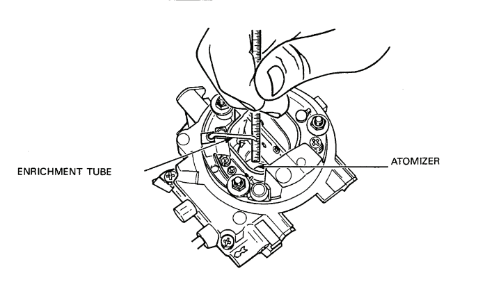
Figure 2-1-6 — Carburetor Enrichment Tube MeasurementClick image to enlarge.
- Position the choke on the carburetor top, ensuring the linkage rod (8) goes into the nylon connector of the bell crank (15).
- Secure the choke body with three Phillips-head screws (11) and lock washers.
- Measure the distance between the end of the enrichment tube (3) and the top of the atomizer, see Figure 2-1-6. The distance should be 24 mm. If necessary, bend the tube up or down until the distance between the tube and atomizer is correct.
- See Figure 2-1-4 and assemble the body:
- Place the “O” ring (3) on the injection tube (2) and insert the tube into the chamber.
- Insert the suction ball (17) into the acceleration pump chamber and install the retaining cap (18). Press the cap into place over the ball.
- Place the spring (19) in the pump chamber.
- Lightly lubricate the pump piston cup with oil and place it in the chamber.
- Secure the pump in the chamber with the guide ring (21).
- Install gasket (12) on the part load enrichment valve (11) and secure it to the body with two Phillipshead screws (10). Ensure the boss with the hole faces up.
- Place “O” ring (4) on the CO adjusting screw (5) and install the screw into the body. Screw it all the way in and then unscrew it five full turns. This is only an approximate adjustment.
- Install the nylon plug (6).
NOTE — If the carburetor is to be installed on the vehicle immediately after re-kitting, install the nylon plug after the final CO adjustment has been completed.
- Place “O” ring (14) on the idle adjustment screw (13) and install the screw. Screw it all the way in and then unscrew it two full turns. This is only an approximate adjustment.
- Install the cutoff valve (9).
- Install the plastic washer (7) on the vacuum advance tube (8).

Figure 2-1-7 — Carburetor Throttle Valve Gap MeasurementClick image to enlarge.
- Using a wire feeler gauge or drill bit, measure the gap between the throttle valve and the throat wall with the throttle valve in the fully closed position, see Figure 2-1-7. The gap should be 0.065 to 0.075 mm. If necessary, turn the screw (16), see Figure 2-1-4, until the gap is within the specific limits. Install a new nylon plug (15).
- Install the gasket (1) on top of the body.
- See Figure 2-1-3 and assemble the subassemblies:
- Place the top of the carburetor on the body and secure with four Phillips-head screws (4) and lock washers.
NOTE — Operate the accelerator pump to ensure the lever is acting on the top of the pump piston.
- Install the intermediate flange (7) to the body and loosely install the socket head screw (5) and spring washer through the accelerator cable bracket.
- Install the two, socket head through bolts (1) and spring washers through the top, body and into the intermediate flange. Tighten all three screws.

Figure 2-1-8 — Carburetor Injection Capacity MeasurementClick image to enlarge.

Figure 2-1-9 — Carburetor Throttle CamClick image to enlarge.
- Install the spacers, flat washers and elastic nuts (2) on the two studs.
- Connect the pulldown hose (9) to the body.
- Connect the carburetor to a source of fuel and hold the carburetor over a funnel and measuring glass, see Figure 2-1-8.
- Turn the choke operating lever so that the choke is fully open and slowly open the throttle valve lever to the fully open position ten times (a minimum of three seconds per stroke). The amount of fuel collected should be 8.5 to 11.5 cm³ (0.299 to 0.404 oz).
- If the fuel collected is not within the specific limits, loosen the clamping screw on the throttle cam and turn the cam clockwise to increase the fuel injection capacity or counter-clockwise to decrease injection capacity, see Figure 2-1-9. Tighten the clamping screw.
13.Installation — To install, proceed as follows:
- Ensure the carburetor and intake manifold mounting surfaces are smooth and free of nicks and cuts.
- Remove the covering from the intake manifold opening.
- Place the carburetor on the intake manifold ensuring the side of the carburetor with the cutoff valve is nearest the valve cover.
- Install the four cap screws, ensuring the ground wire is attached to the cap screw under the cutoff valve.
- Tighten the four cap screws.
- Connect the fuel line to the carburetor.
- Connect the vacuum advance line to the carburetor.
- Connect the electrical lead to the cutoff valve terminal.
- Push the choke cable, casing and hose through the bracket until the hose protrudes slightly past the bracket to ensure the clamp will hold the casing and tighten the screw.
- Insert the choke cable through the control arm at the carburetor.
- With the choke fully open and the choke control knob at the dash pushed fully in, tighten the screw on the control lever. Ensure the choke opens and closes completely.
- Push the accelerator cable and casing with the grommet through the accelerator cable bracket. Place the cable tip in the socket of the sector plate and install the clip on the cam.

Figure 2-1-10 — Accelerator Cable AdjustmentClick image to enlarge.
- Adjust the accelerator cable until there is a maximum of 1 mm clearance between the throttle sector plate and the stop with the accelerator pedal in the full-throttle position, see Figure 2-1-10, and install a spring clip on each side of the accelerator cable bracket.
- Check the clearance between the throttle sector plate and stop a second time with the accelerator pedal in the fullthrottle position. Adjust the clearance, if necessary.
- Install the air inlet hose from the carburetor to the air cleaner assembly. Position the clamp screw away from the washers.
- Install the breather hose on the valve cover.
- Perform necessary adjustments (refer to Section 8).
Fuel Filter Assembly (Spin-on Type)

Figure 2-1-11 — Fuel Filter InstallationClick image to enlarge.
14.Removal — To remove, see Figure 2-1-11 and proceed as follows:
- Ensure the battery master switch is off.
- Tag fuel lines to ensure correct installation.
- Place a container under the filter to collect any fuel spillage.
- Disconnect the fuel inlet, outlet and return lines at the fuel filter.
- Remove the screws, flat washers and the self-locking nuts which secure the fuel filter to the inner fender well and remove the filter assembly.
15.Installation — To install, see Figure 2-1-11 and proceed as follows:
- Install the fuel filter to the inner fender well and secure using the previously removed screws, washers and new selflocking nuts.
- Install and secure the fuel inlet, outlet and return lines to the correct locations on the filter.
- Remove the container and turn on the battery master switch.
- Turn the ignition switch 'ON' or start the engine and check for leaks.
Fuel Pump
16.Removal — To remove, proceed as follows:
- Turn off the battery master switch.
- Support the weight of the vehicle and remove the right rear wheel.
- Remove the fuel tank protection plate.
- Wrap a rag around the outlet hose at a point near the tank and squeeze the hose closed with vise-grips.
- Place a drain pan under the fuel pump. Remove the banjo bolts from the top and bottom of the pump and remove the two copper washers from each hose fitting.
- Disconnect the electrical wire from the pump.
- Remove the cap screw, washer and the ground wire from the pump bracket.
- Remove the two elastic nuts and washers and remove the pump and bracket.
- Remove the pump from the bracket.
- Check the two rubber mounts on the vehicle for serviceability. If necessary, unscrew the mounts and install new mounts.
17.Installation — To install, proceed as follows:
- Place the pump on the bracket, ensuring the pump outlet is at the top. Install two cap screws and flat washers and torque to 10 N•m (7 ft lb).
- Place the pump bracket on the rubber mounts and install two flat washers and two new elastic nuts. Do not twist the rubber mounts excessively.
- Install the ground wire to the pump bracket with a cap screw and starwasher. Ensure there is a clean electrical connection.
WARNING — Ensure the outlet hose from the fuel tank does not touch the inner constant velocity joint.
- Place new copper washers on both sides of each hose fitting and install each hose to the pump with a banjo bolt. Ensure the outlet hose from the fuel tank is connected to the bottom of the pump.
- Connect the electrical wire to the pump electrical terminal.
- Remove the vise-grips and rag from the outlet hose.
- Turn on the battery master switch.
- Turn the accessory switch “ON”.
- Ensure the pump is operating correctly and check for leaks.
- Install the right rear wheel and wheel bolts. Remove the axle stand. Torque the wheel bolts to 175 N•m (129 ft lb).
- Install the fuel tank protection plate.
Fuel Tank
18.Removal — To remove, proceed as follows:
- Disconnect the battery ground lead.
- Tilt the rear seats forward.
- Remove the five floor panels.
- Remove the four floor panel rails and note the location of the spacer pads and long cap screws.

Figure 2-1-12 — Fuel Tank Access PlateClick image to enlarge.
- Remove the fuel tank access plate, see Figure 2-1-12.
- Remove the rear seat belt securing bolt from either one of the rear fender well panels.
- Clean the top of the tank.
- Remove the return line from the fuel tank sending unit and cover the opening to prevent contamination.
- Disconnect electrical wires #28 and #90E from the sending unit.
- Remove the two strap bolts and pins and swing the straps away from the tank.
- Remove the vent hose clamp from the top of the tank and place it out of the way.
- Cover the vent opening.
- Remove the fuel tank protection plate.
- Clean the bottom of the tank and the outlet hose.
- Place a suitable container under the tank outlet.
- Pull the outlet hose away from the tank and allow the gasoline to drain into the container.
- Remove the strainer from the tank or the outlet hose.
- Cover the tank outlet.
- Loosen the clamps that secure the filler neck hose to the tank.
- Remove the four cap screws from the filler neck plate and pull the filler neck and rubber hose away from the vehicle.
- Cover the tank inlet.
- Remove the tank by lifting up on the right-hand side to work the filler neck portion from under the left fender well.
19.Installation — To install, proceed as follows:
- Clean the surface of the tank.
- Inspect the tank retaining straps and protection strips and replace if damaged.
- Ensure the tank openings are covered.
- Lower the tank onto the vehicle frame and ensure the tank filler neck fits under the left fender well.
- Remove the protective covering from the filler neck.
- Inspect the filler neck rubber hose and gasket for damage and replace if necessary.
- Install the filler neck and gasket to the rear of the vehicle with the four cap screws and lock washers.
- Slide the rubber hose down over the tank filler neck and tighten the hose clamps.
- Install the vent hose and clamp on top of the tank.
- Connect electrical wire #28 to the positive terminal of the sending unit and #90E to the negative, terminal.
- Install the return line on the sending unit.
- Install the retaining straps on the tank. Ensure the protection strips are in place, and install a strap bolt and pin in each strap.
- Install a new or cleaned strainer in the tank outlet.
- Install the outlet line.
- Partially fill the tank with gasoline and inspect the tank connections for leaks.
- Connect the battery ground cable and check that the sending unit is operating correctly.
- Install the protection plate.
- Apply a coat of sealant around the access plate opening and install the access plate.
- Install the rear floor panels and rails (refer to Part 6, Section 2), ensuring the spacer pads and the long bolts are positioned correctly.
- Install the rear seat belt securing bolt to the fender well panel.
Fuel Tank Sending Unit
20.Removal — To remove, proceed as follows:
- Disconnect the battery ground lead.
- Tilt the rear seats forward.
- Remove the centre floor panel.
- Remove the four cap screws from the sending unit access plate and remove the plate.
- Clean the area around the sending unit.
- Remove the return line from the sending unit.
- Disconnect electrical wire #28 and #90E from the sending unit terminals.

Figure 2-1-13 — Fuel Tank Sending Unit Cap RemovalClick image to enlarge.
CAUTION — To prevent damage to the inlet on the sending unit, ensure the wrench fits securely on the sending unit cap.
- Unscrew the sending unit cap, using special wrench Matra tool 2012A, see Figure 2-1-13.
- Remove the sending unit and cover the tank opening.
- Remove the gasket from the sending unit.
21.Installation — To install, proceed as follows:
- Install a new gasket on the sending unit.
- Install the sending unit into the tank, ensuring the inlet on the sending unit points toward the front of the vehicle.
CAUTION — To prevent damage to the inlet on the sending unit, ensure the wrench fits securely on the sending unit cap.
- Using special wrench Matra tool 2012A, screw the sending unit cap onto the tank.
- Install the return line to the inlet on the sending unit.
- Connect electrical wire #28 to the positive terminal of the sending unit and #90E to the negative terminal.
- Connect the battery ground cable.
- Turn the accessory switch “ON” and check for leaks.
- Ensure the sending unit is operating correctly.
- Apply a coat of sealant to the area around the sending unit access plate opening.
- Install the access plate.
- Install the centre floor panel.
Fuel Tank Strainer
22.Removal — To remove, proceed as follows:
- Remove the fuel tank protection plate.
- Remove the outlet hose and drain the gasoline into a suitable container.
NOTE — The strainer may come out when the hose is disconnected from the outlet.
- Remove the strainer from the tank.
23.Installation — To install, proceed as follows:
- Clean the strainer with compressed air.
- Install the strainer into the tank outlet.
- Install the outlet hose.
- Fill the tank with gasoline and check for leaks.
- Install the fuel tank protection plate.
Fuel Tank Filler Neck
24.Removal — To remove, proceed as follows:
- Clean around the fuel tank filler neck.
- Loosen the hose clamps on the filler neck connecting hose and slide the hose up the filler neck and off the tank. Cover the tank opening.
- Remove the tank vent hose from the filler neck.
- Remove the four cap screws, lock and flat washers from the filler neck plate.
- Remove the filler neck.
25.Inspection — To inspect, proceed as follows:
- Inspect the filler neck connecting hose for damage and replace, if necessary.
- Inspect the filler neck gasket for damage and replace, if necessary.
26.Installation — To install, proceed as follows:
- Install the filler neck to the rear of the vehicle with four cap screws, lock and flat washers.
- Uncover the tank inlet and install the filler neck connecting hose.
- Install the tank vent line to the filler neck.
- Secure the clamps.
Accelerator Cable
27.Removal — To remove, proceed as follows:
- Remove the clip from the cam of the throttle linkage and disconnect the cable tip from the cam.
- Remove the two spring clips on each side of the rubber grommet at the accelerator cable mounting bracket and pull the grommet and cable out of the bracket.
- Disconnect the securing clip at the bracket on the valve cover and remove the clip from the cable.
- Disconnect the cable from the accelerator pedal arm by pulling up on the cable.
- Pull the cable and casing from the grommet in the firewall and pry the grommet from the firewall.
- Pull the accelerator cable through the firewall into the engine compartment.
28.Installation — To install, proceed as follows:
- Insert the pedal end of the accelerator cable through the firewall.
- Push the grommet on the cable and into the hole in the firewall.
- Push the cable and casing into the grommet.
- Connect the end of the cable to the end of the accelerator pedal arm.
- Insert the rubber grommet on the cable into the cable bracket, place the cable tip in the cam of the sector plate, and install the clip on the cam.
- Adjust the accelerator cable until there is a maximum clearance of 1 mm between the throttle sector plate and the stop with the accelerator pedal in the full-throttle position, see Figure 2-1-10, and install a spring clip on each side of the accelerator cable bracket.
- Check the clearance between the throttle sector plate and stop a second time with the accelerator pedal in the fullthrottle position. Adjust the clearance, if necessary.
- Install the cable securing clip on the bracket on the valve cover.
Choke Control Cable
29.Removal — To remove, proceed as follows:
- Disconnect the cable at the choke lever.
- Pull the cable through the casing and dash.
30.Installation — To install, proceed as follows:
- Insert the cable through the dash and casing.
- Insert the cable through the choke lever.
- Ensure the choke lever is fully open and the knob is pushed all the way in. Tighten the screw on the lever.
Choke Control Cable Casing
31.Removal — To remove, proceed as follows:
- Remove the choke control cable.
- Loosen the casing clamp at the carburetor and remove the casing.
- Disconnect the casing from the clip on the high tension (HT) cable.
- Remove the rubber protection hose from the casing.
- Remove the grommet from the firewall and remove the casing.
- Remove the switch panel from the dash.
- Squeeze the grommet on the casing behind the dash and pull the casing and grommet through the dash.
32.Installation — To install, proceed as follows:
- Insert the casing and grommet into the dash until the grommet is flush with the dash.
- Push the casing through the firewall.
- Install the grommet onto the casing and insert it into the firewall.
- Install the rubber protection hose over the casing.
- Insert the casing into the clamp on the carburetor.
- Ensure the casing protrudes slightly past the bracket to ensure the clamp will hold the casing and tighten the clamp.
- Connect the clip from the HT cable onto the casing.
- Install the choke cable and ensure the choke opens and closes completely.
- Install the switch panel to the dash.
Throttle Cable
33.Removal — To remove, proceed as follows:
- Loosen the screw on the cable stop and remove the stop.
- Pull the cable through the dash.
34.Installation — To install, proceed as follows:
- Insert the cable into the dash.
- Pull the cable fully into the dash while feeding the end of the cable through the stop bracket on the firewall.
- With the bracket tilted away from the firewall, install the stop on the cable against the bracket.
- Tighten the screw on the stop.
Section 2 — Intake and Exhaust System
General
Description of Air Intake System
1.The air intake system consists of the following:
- air intake grille,
- Dynacell dry type air filter with moisture separator,
- air intake temperature regulator box,
- coolant heated aluminum intake manifold,
- intake valves,
- air ducts and hoses.
Operation of Air Intake System
2.Fresh air is drawn through a grille at the centre rear of the hood and into the air duct. When the intake air is below 25°C (77°F), a sensor (thermostat) in the regulator box closes a valve preventing ambient air from entering the filter and carburetor. Via a flexible hose, air is directed from the regulator box to the exhaust pipe heat stove where the air is heated and returned to the regulator box via another flexible hose. The heated air is then drawn into the air cleaner and carburetor.
3.As the intake air is heated, the sensor gradually opens the valve, allowing ambient air to mix with the heated air.
4.When the intake air is above 25°C (77°F), there is no requirement for heating. The sensor holds the valve in the open position blocking off the flexible hose to the heat stove and the air is directed to the air filter.
5.Under both conditions, the air, direct from the air duct or from the heat stove, leaves the regulator box and enters the air filter. At the air filter, moisture is removed from the air by the internal baffling. Moisture that collects in the air filter housing is removed by two automatic drain valves in the bottom. The air passes through the air filter element, where dirt/dust is removed, and enters a duct leading to the carburetor.
6.The air is then mixed with gasoline in the proper ratio required for combustion and enters the aluminum intake manifold. The air/fuel mixture is then heated again by coolant which passes through a passage in the bottom of the intake manifold. The mixture then enters the cylinder for combustion.
Description of Exhaust System
7.The exhaust system consists of the following:
- exhaust valves,
- cast iron exhaust manifold,
- exhaust pipe,
- heat stove,
- muffler,
- tail pipe,
- heat shields and hangers.
Operation of Exhaust System
8.Exhaust gases flow past the exhaust valves into the cast iron exhaust manifold and into the exhaust pipe. Hot exhaust gases warm the intake air passing through the heat stove. The exhaust gases then move through the muffler and into the tail pipe which is located high inside the right rear bumper to permit fording. The complete exhaust system is supported by rubber hangers and mounts. Heat shields have been placed over the muffler to prevent excessive heat on the cab floor and over the exhaust pipe and tail pipe under the drive axles to deflect heat from the axle dust boots.
Component Removal and Installation
WARNING — Do not replace metric bolts with standard bolts. See WARNING at front of manual.
Air Intake Regulator Box
9.Removal — To remove, proceed as follows:
- Remove the two screws from the air intake regulator box and the filter housing.
- Loosen the clamp from the air intake duct hose.
- Remove the preheat hose from the regulator box.
- Pull the hose clear of the inlet duct and withdraw the regulator box from the air cleaner assembly.
10.Inspection — To ensure the thermostatic sensor in the air intake regulator box operates correctly, proceed as follows:
- Place the end of the regulator box under warm tap water. The valve in the regulator box should open.
- Place the end of the regulator box under cold tap water. The valve in the regulator box should close.
- Replace the sensor, if the valve does not operate correctly.
11.Installation — To install, proceed as follows:
- Insert the end of the air intake regulator box into the air cleaner assembly and install the two screws.
- Install the intake hose on the duct.
- Install the preheat hose on the regulator box.
Thermostatic Sensor
12.Replace — To replace the thermostatic sensor in the air intake regulator box, proceed as follows:
- Carefully remove the plastic protector from the sensor.
- Remove the nut from the sensor and remove the sensor from the regulator box.
- Install a new sensor in the regulator box and install the nut.
- Carefully install the plastic protector on the new sensor.
Air Intake Duct
13.Removal — To remove, proceed as follows:
- Remove the air intake regulator box.
- Disconnect the preheat hose from the air intake duct.
- Remove the four nuts from the duct and remove the duct from the firewall.
14.Installation — To install, proceed as follows:
- Place the duct on the mounting studs on the firewall and install the four nuts.
- Connect the preheat hose.
- Install the air intake regulator box.
Air Cleaner Assembly
15.Removal — To remove, see Figure 2-2-1 and proceed as follows:

Figure 2-2-1 — Air Cleaner AssemblyClick image to enlarge.
- Loosen the two locking nuts on the air cleaner clamping strap and remove the strap.
- Pull up on the top front of the filter element.
- Remove the element from the housing.
- Remove the two screws and pull the air intake regulator box from the filter housing.
- Remove the distributor ventilation hose from the fitting on the filter housing.
- Remove the carburetor air intake hose at the filter housing.
- Remove the four securing nuts from the housing.
- Lift out the housing
16.Installation — To install, see Figure 2-2-1 and proceed as follows:
- Install the filter housing on the mounting studs and install the four nuts.
- Install the end of the regulator box into the filter housing, ensuring the bolt holes are aligned and install the two screws.
- Install the distributor ventilation hose to the fitting on the filter housing.
- Install the carburetor air intake hose to the filter housing.
- Reinstall the filter element with the open end against the gasketed surface of the housing. Push the element forward and downward until the gasket seats squarely against the sealing surface of the housing.
CAUTION — Do not overtighten the clamping strap. To do so will cause the sides of the filter element to bow and can distort the sealing lip in the housing.
- Install the clamping strap and crosstighten the nuts evenly.
Intake Manifold
17.Removal — To remove, proceed as follows:
- Remove the carburetor (refer to Section 1).
- Remove the brake servo vacuum line.
- Remove both coolant hoses from the manifold and place in a high position to avoid loss of coolant.

Figure 2-2-2 — Intake/Exhaust Manifold BracketClick image to enlarge.
- Remove the cap screw from the intake/exhaust manifold bracket, see Figure 2-2-2.
- Loosen the nut on the bracket and swing the bracket down.
- Remove the six socket head cap screws and remove the manifold and gasket.
18.Inspection — To inspect, proceed as follows:
- Using a straight edge, check the mating surfaces of the manifold for distortion.
- Clean around the ports and ensure the mating surfaces are smooth.
19.Installation — To install, proceed as follows:
- Install a new gasket on the manifold ports and place the manifold on the cylinder head.
- Install a cap screw at each end to hold the gasket and manifold to the cylinder head and install the four remaining cap screws ensuring the gasket does not slip. Torque to 25 N•m (18 ft lb).
- Swing the intake/exhaust manifold bracket into position and install the cap screw. Torque the cap screw to 20 N•m (15 ft lb) and the nut to 25 N•m (18 ft lb).
- Install the coolant hose from the rear of the cylinder head to the bottom coolant opening on the manifold.
- Install the other coolant hose to the top coolant opening.
- Install the brake servo hose to the intake manifold.
- Install the carburetor (refer to Section 1).
Exhaust Manifold
20.Removal — To remove, proceed as follows:
- Remove the six nuts securing the exhaust pipe to the manifold.
- Pull the exhaust pipe away from the manifold and remove the gasket.
- Remove the eight nuts and flat washers from the manifold.
- Remove the cap screw from the intake/exhaust manifold bracket.
- Loosen the nut on the exhaust manifold and swing the bracket out of the way.
- Remove the manifold and four gaskets.
21.Inspection — To inspect, proceed as follows:
- Inspect the manifold for cracks.
- Using a straight edge, check the mounting surfaces for distortion. If necessary, surface grind until flat.
22.Installation — To install, proceed as follows:
- Install new gaskets and manifold on the cylinder head, ensuring the gaskets are correctly positioned.
- Install eight nuts and flat washers and torque to 25 N•m (18 ft lb).
- Swing the exhaust manifold bracket into position.
- Install a cap screw through the bracket and into the intake manifold and torque to 20 N•m (15 ft lb).
- Torque the nut on the exhaust manifold bracket to 25 N•m (18 ft lb).
- Install a new gasket on the exhaust pipe and fit the pipe to the manifold, ensuring the gasket is correctly positioned.
- Install the six nuts and torque to 20 N•m (15 ft lb).
Exhaust System
WARNING — To prevent injury, if the engine has been operating, let the exhaust system cool before removing.
23.Removal — To remove, proceed as follows:

Figure 2-2-3 — Wishbone ArmClick image to enlarge.

Figure 2-2-4 — Muffler HangerClick image to enlarge.
- Remove the right front and right rear wheels.
- Remove the six nuts securing the exhaust pipe to the manifold, lower the exhaust pipe and remove the gasket.
- Remove the wishbone mounting bolts at the vehicle frame from the rear arm of the rear suspension, and the front arm of the front suspension.
- Remove the wishbone mounting bolts and nuts at the front and rear ball joints.
- Loosen the front and rear shock absorber lower mounting bolts.
- Swing both wishbone arms down, clear of the vehicle frame, see Figure 2-2-3.
- Remove the nut and bolt from the muffler hanger, see Figure 2-2-4.
- Remove the three nuts, bolts and lock washers securing the exhaust pipe to the muffler locking collars.
- Lower the exhaust pipe slightly and remove the two preheat hoses from the stove.
- Remove the exhaust pipe.
- Remove the three nuts, bolts and lock washers securing the muffler to the tail pipe locking collars.
- Remove the muffler hangers from the two rubber hangers.
- Remove the tail pipe from the two rubber hangers.
24.Inspection — Inspect the rubber hangers and replace if cracked or broken.
25.Installation — To install, proceed as follows:
- Insert the tail pipe from the rear of the vehicle.
- Place the muffler under the vehicle and install on the two corresponding rubber hangers.
- Install a new gasket between the tail pipe and the muffler locking collars.
- Slide the locking collars of the tail pipe and muffler together and install the three bolts and self-locking nuts, but do not tighten.
- Hook the tail pipe to the two rubber hangers.
- Insert the exhaust pipe from the front of the vehicle.
- Install the two preheat hoses to the stove.
- Install a new gasket on the exhaust manifold mounting studs and install the exhaust pipe to the manifold.
- Install the muffler to the hanger using a nut and bolt, but do not tighten.
- Install a nut to each of the exhaust manifold mounting studs, but do not tighten.
- Place a new gasket between the exhaust pipe and muffler locking collars and secure with three bolts and selflocking nuts, but do not tighten.
- Ensure there is sufficient clearance between exhaust components and body and that the rubber hangers are evenly stressed.
- Tighten all exhaust system bolts and nuts.
- Swing the wishbone arms into place. Install the mounting bolts at the vehicle frame, and torque to 150 N•m (111 ft lb).
- Install the wishbone arm mounting bolts in the front and rear ball joints and torque to 200 N•m (148 ft lb).
- Tighten the front and rear shock absorber lower mounting bolts and torque to 200 N•m (148 ft lb).
- Install the wheels and torque to 175 N•m (129 ft lb).
- Start the engine and check the exhaust system for leaks.
Section 3 — Cooling System
General
Description of the Cooling System
1.The pressurized cooling system consists of a cross-flow radiator, two electrically-driven fans, two thermoswitches, thermostat, coolant pump, expansion reservoir, block heater, heater and connecting hoses.
Operation of the Cooling System
2.A radiator and two thermostaticallycontrolled electrically-driven fans dissipate the heat generated by the engine. A centrifugal coolant pump circulates engine coolant through the cooling system. The thermostat, located in the thermostat housing at the bottom of the coolant pump housing, maintains a normal operating temperature range of 90°C to 95°C (194°F to 203°F).
3.The cooling system is pressurized to raise the boiling point of the coolant.
4.The coolant pump circulates engine coolant from the lower part of the radiator, through the thermostat housing at the bottom of the coolant pump and into the cylinder block.
5.When coolant temperature is below the engine operating temperature, coolant circulation is restricted at the thermostat housing. A by-pass permits coolant circulation within the engine during the warm-up period.
6.From the cylinder block the coolant passes through the cylinder head and the intake manifold. When the engine is at normal operating temperature, coolant returns to the top of the radiator and passes through a series of tubes where it is cooled before recirculating through the system.
Radiator
7.Operation — Coolant flows from the engine to the radiator, and through the radiator tubes for recirculation to the engine. The coolant in the tubes is cooled by air passing across the radiator core.
Cooling System Fans and Thermoswitches
8.Description — The fan assembly consists of two electrically-driven fans, each connected to thermoswitches located in the radiator. The fans do not necessarily operate simultaneously as the switches are one above the other. There is a 5°C coolant temperature difference between the two thermoswitch locations.
9.Operation — When the coolant temperature increases, the thermoswitches will activate the fan motors. When the coolant in the radiator is sufficiently cool, the thermoswitches will switch off the fan motors.
Thermostat
10.Description — A thermostat, located in the thermostat housing at the bottom of the coolant pump, controls the coolant temperature in the engine.
11.Operation — At coolant temperatures below approximately 85°C (185°F), the thermostat valve remains closed and blocks the flow of coolant through the radiator. During this period, coolant flows through the coolant pump, cylinder block, cylinder head and thermostat housing by-pass hose. As the coolant temperature rises, the thermostat valve begins to open, allowing the coolant to circulate through the radiator and the engine.
Coolant Pump
12.Description — A centrifugal coolant pump, located at the front of the engine block on the left side, is belt-driven by the crankshaft pulley.
13.The pump assembly consists of an impeller, which is a press-fit on one end of the coolant pump shaft and a coolant pump drive pulley hub, which is a press-fit on the other end. The pump shaft is sealed in a bearing housing and requires no lubrication or maintenance. A pulley is bolted to the pulley hub. The bearing housing is bolted to the pump housing.
14.Operation — The pump causes the coolant to circulate through the cylinder block, cylinder head, intake manifold coolant jacket, radiator and heater.
Expansion Reservoir
15.Description — The expansion reservoir provides additional coolant capacity and acts as a coolant expansion chamber. The reservoir is located on the left fender well panel in the engine compartment.
16.Operation — A small diameter breather hose from the expansion reservoir to the radiator upper tank prevents air entrapment in the radiator. The large diameter hose attached to the bottom of the expansion reservoir allows coolant flow from the reservoir to the bottom of the radiator to allow for coolant expansion.
Block Heater
17.The block heater is an electrical element installed in the engine block in lieu of a frost plug. The element operates on 110 volts AC. As the coolant is warmed by the heater, the coolant rises in the block and is replaced-by cold coolant which results in the coolant circulating through the engine by convection.
Coolant Temperature Sending Units
18.There are two temperature sending units in the cooling system at the rear of the cylinder head. One unit controls the temperature gauge, and the other unit controls the temperature warning light.
Heater Assembly
19.The heater blower motor is electrically operated and controlled by a two-speed switch. Air is forced by the blower fan across the heater core which is filled with coolant from the cooling system. This forced air is heated as it passes the core and enters the interior of the vehicle by way of the footwell vents and through the defroster duct to the bottom of the windshield. When the footwell vents are closed, all of the warm air is directed through the defroster duct.
Component Removal and Installation
WARNING — Do not replace metric bolts with standard bolts. See WARNING page at the front of the manual.
Radiator and Fan Assembly
WARNING — To prevent injury, allow the engine to cool before removing the radiator and fan assembly if the engine has been operating.
20.Removal — To remove the radiator and fan assembly, proceed as follows:
WARNING — To prevent injury, ensure the battery master switch is off before removing the fan assemblies.
- Turn off the battery master switch.
- Remove the engine protection plate.
- Remove the two bolts from the radiator guard.
- Drain the cooling system (refer to Section 8).
- Remove the breather hose from the radiator.
- Remove the upper and lower coolant hoses from the radiator.
- Remove the coolant return hose from the radiator.
- Disconnect the electrical connectors from the two fan thermoswitches.
- Remove the cap screw from the fan ground wires on the left fender well.
- Remove the two self-locking nuts and washers securing radiator to the radiator mounting bracket.
- Remove the two nuts and washers securing the top of the radiator to the grille.
NOTE — The mounts remain with the radiator.
- Lift the radiator and fan assembly from the vehicle.
NOTE — When removing the radiator and fan assembly in preparation for power pack removal, remove the four slotted screws, flat and lock washers from the radiator mounting bracket and remove the bracket.
21.Inspection — Inspect and replace the radiator rubber mounts, if unserviceable.
22.Installation — To install, proceed as follows:
- Position the assembly, ensuring the two bottom radiator mounting bolts are aligned with the radiator mounting bracket holes.
- Install the two nuts and washers securing the top of the radiator to the grille.
- Install the two nuts and washers securing the bottom of the radiator to the mounting bracket.
- Install the electrical wiring from the fans as follows:
- Connect wires #85 and 85A to the bottom thermoswitch terminals.
- Connect wires #84 and 84A to the top thermoswitch terminals.
CAUTION — If the ground wires are not attached, the fans will not operate and the engine will overheat.
- Attach ground wires #96A and 96B to the left fender well and install the cap screw.
- Install the coolant return hose to the radiator.
- Install the lower and upper radiator coolant hoses.
- Install the breather hose on the top of the radiator.
- Fill the cooling system (refer to Section 8).
- Install the radiator guard with the two bolts.
- Install the engine protection plate.
- Turn on the battery master switch.
NOTE — When installing the radiator and fan assembly during power pack installation, position the radiator mounting bracket and install four slotted screws, flat and lock washers.
Fan Assemblies
23.Removal — To remove, proceed as follows:
WARNING — To prevent injury, ensure the battery master switch is off before removing the fan assemblies.
- Turn the battery master switch off.
- Disconnect the fan ground leads from the left fender well panel.
- Disconnect the wires from the thermoswitches.
- Remove, through the holes in the radiator support bracket, the two cap screws at the bottom of the fan shroud.
- Remove the three cap screws from the top of the shroud and lift out the fan assemblies.
24.Disassembly — To disassemble, proceed as follows:
- Disconnect the electrical leads from the terminals on the fan motors.
- Remove the three nuts from each fan and remove the fan assemblies from the shroud.
- Straighten the lock tab on each fan.
- Remove the left-hand threaded nuts from both motor shafts.
- Remove the fans from the motor shafts.
25.Assembly — To assemble, proceed as follows:
- Place the fans on the motor shafts and install a locking tab washer on each shaft with the two inner tabs of each washer aligned with the flats of each shaft.
- Install the left-hand threaded nuts on both motor shafts and bend the lock tabs of the washers against the mounts.
26.Installation — To install, proceed as follows:
- Place the fan assemblies in the shroud and install three nuts on each assembly.
- Connect wires #96C and #96B to the terminals of the right-hand motor and jumper wire from #96C to a stud.
- Connect wires #96A and #96 to the terminals of the left-hand motor and jumper wire from #96 to a stud.
- Install the fan assemblies on the radiator and secure the top of the shroud to the radiator with three cap screws.
- Install through the holes in the radiator support bracket, two cap screws to secure the bottom of the shroud to the radiator.
- Install the screws on the right side and bottom right corner of the shroud.
- Connect the fan electrical connectors to the thermoswitches, ensuring leads #84 and #84A are connected to the top thermoswitch and leads #85 and #85A are connected to the bottom thermoswitch.
- Connect the fan ground leads to the fender well panel.
- Turn on the battery master switch.
- Start the engine and ensure the fans operate.
Fan Thermoswitches
27.Test — The test procedure for both thermoswitches is the same. If one or both fans fail to operate, check the coolant temperature. If the coolant temperature is above 96°C (204°F), test the thermoswitches. To test, proceed as follows:
- Disconnect the wires from the thermoswitch and, using an insulated length of wire, bridge the two thermoswitch wires.
- If the fan does not operate, check the wiring to the thermoswitch. If the fan operates, the thermoswitch is defective and must be replaced.
28.Removal — The removal procedure for both thermoswitches is the same. To remove, proceed as follows:
- Turn off the battery master switch.
- Drain the radiator (refer to Section 8).
- Disconnect the upper radiator hose from the radiator.
- Using a 30 mm wrench, hold the nut nearest the radiator that is on the thermoswitch and, using a 30 mm wrench, unscrew the thermoswitch from the radiator.
29.Installation — The installation procedure for both thermoswitches is the same. To install, proceed as follows:
- Place a new gasket on the new thermoswitch and install the thermoswitch in the radiator.
- Connect the wires to the thermoswitch.
- Connect the upper radiator hose to the radiator.
- Add coolant to the expansion reservoir until the coolant is level with the arrow marked on the side of the expansion reservoir.
- Turn on the battery master switch and start the engine.
- Check for leaks in the cooling system and ensure the fans are operating.
Coolant Thermostat
30.Removal — To remove the thermostat, follow the procedure for draining the cooling system (refer to Section 8).
31.Inspection — To inspect, proceed as follows:

Figure 2-3-1 — Coolant Thermostat MeasurementsClick image to enlarge.
- Measure the thermostat to determine dimension A, see Figure 2-3-1. The distance should be not less than 31 mm. If the distance is greater than 31 mm, the valve is not closing completely.
- Place the thermostat and a thermometer in water and heat the water.
- When the thermostat starts to open, check the water temperature. The thermostat should begin to open at approximately 87°C (188°F) and should be fully open at approximately 102°C (215°F).
- With the thermostat fully open, measure the thermostat to determine dimension B, see Figure 2-3-1. This distance should be a minimum of 38 mm.
32.Installation — Inspect all thermostats before installation. To install a thermostat, follow the procedure for filling the cooling system (refer to Section 8).
Coolant Pump
33.Removal — To remove, proceed as follows:
- Remove the engine protection plate.
- Drain the cooling system (refer to Section 8).
- Loosen the three socket head screws on the coolant pump pulley.
- Loosen the alternator mounting and adjusting bolts and remove the drive belts.
- Remove the bolt, nut and lock washer from the lower timing belt cover at the corner of the coolant pump.
- Remove the two coolant hoses at the pump.
- Remove the four coolant pump cap screws and remove the pump and “O” ring.
- Remove the three socket head screws and remove the pulley.
34.Disassembly — To disassemble, proceed as follows:
- Remove the seven bolts and washers that secure the bearing housing of the pump to the housing, and remove the bearing housing and gasket.
- Remove the two cap screws and washers securing the thermostat housing to the pump and remove the thermostat housing, thermostat and “O” ring.
35.Assembly — To assemble, proceed as follows:
- If the pump seal was leaking or the bearing is seized or excessively worn, replace the bearing housing.
- Place a new gasket on the housing and secure the bearing housing with the seven cap screws and washers. Tighten the cap screws a little at a time and torque to 10 N•m (7 ft lb).
- Install a new “O” ring on the thermostat housing and install the thermostat and housing on the pump. Torque the cap screws to 10 N•m (7 ft lb).
36.Installation — To install, proceed as follows:
- Place the pulley on the new pump and install the three socket head cap screws but do not tighten.
- Position the pump and “0” ring on the engine block and install the four cap screws with the two long cap screws in the two bottom mounting holes. Torque the four cap screws to 10 N•m (7 ft lb).
- Ensure a thermostat has been installed. If a thermostat has not been installed, install a new thermostat (refer to Section 8).
- Connect the three coolant hoses to the pump.
- Install the bolt, lock washer and nut in the lower timing belt cover at the coolant pump.
- Install the drive belts and adjust belt deflection to 15 mm.
- Torque the three pulley socket head screws to 20 N•m (15 ft lb).
- Fill the cooling system (refer to Section 8).
- Check for leaks.
- Install the engine protection plate.
Expansion Reservoir
37.Removal — To remove, proceed as follows:
- Remove the breather hose from the top of the reservoir.
- Remove the three cap screws and flat washers that secure the reservoir to the fender well panel.
- Turn the reservoir upside-down and remove the hose from the bottom of the reservoir, ensuring the end of the hose is kept upright to prevent the coolant from draining.
- Drain the coolant from the expansion reservoir.
38.Installation — To install, proceed as follows:
- Install the lower radiator hose to the bottom of the reservoir.
- Install the breather hose to the top of the reservoir.
- Place the reservoir on the fender well panel and install the three cap screws and flat washers, ensuring the longest cap screw is installed at the rear of the reservoir.
- Add coolant to the reservoir to top up the system.
Heater Assembly
39.Removal — To remove, proceed as follows:
- Turn off the battery master switch.
- Remove the cap from the expansion reservoir.
- Remove the speedometer head cover.
- Remove the defroster duct (refer to Part 6, Section 2).

Figure 2-3-2 — Heater Assembly Control ValveClick image to enlarge.
- Remove the heater hose at the heater and drain the coolant into a suitable container.
- Remove the control valve from the heater assembly by removing the two bolts, see Figure 2-3-2.
- Disconnect the electrical connector at the back of the heater assembly.
- Remove the bottom bolt and nut from the heater retaining strap.
- Remove the heater assembly.
40.Disassembly — To disassemble, proceed as follows:
- Remove the two screws on the left side of the heater core.
- Remove the core from the assembly.
- Remove the screw from the fan at the motor shaft.
- Remove the fan blade.

Figure 2-3-3 — Heater Fan Assembly Resistor and SuppressorClick image to enlarge.
- Disconnect the electrical wire from the terminal on the resistor, see Figure 2-3-3.
- Remove the two resistor screws from the fan housing.
- Remove the resistor.
- Pull up the centre terminal on the fan housing using a pair of pliers and remove the wedge.
- With the terminal fully up, use a small screwdriver and push in on the locking tab on the terminal.
- Push the terminal connector and wire down through the housing.
- Remove the nut from the suppressor at the fan housing, see Figure 2-3-3.
- Remove the suppressor from the suppressor cable and mounting bolt.
- Push the heater motor down and out of the fan housing, ensuring the suppressor and wires are not damaged.
41.Assembly — To assemble, proceed as follows:
- Insert the wire and then the motor into the fan housing.
- Attach the suppressor and ground cable.
NOTE — Install the ground strap so that it is in line with the suppressor mounting strap on the heater housing.
- Install the connector on the centre terminal.
- Pull the connector fully up and bend the locking tab.
- Install the wedge in the terminal. If necessary, hold the connector in position.
- Position the fan blade so that the locking screw is on the flat of the shaft.
- Install the fan blade with the locking screw.
- Insert the heater core into the housing.
- Install the two screws and washers.
42.Installation — To install, proceed as follows:
- Position the heater under the dash and install the retaining strap bolt and nut.
- Connect the 3-pronged electrical plug to the terminal at the back of the heater assembly.
- Install the control valve on the heater.
- Connect the heater hose to the heater.
- Top up the cooling system (refer to Section 8).
- Install the cap on the expansion reservoir.
- Install the defroster duct (refer to Part 6, Section 2).
- Install the speedometer head cover.
Block Heater
43.Removal — To remove, proceed as follows:
- Drain the cooling system (refer to Section 8).
- Disconnect the electrical plug from the block heater.
- Loosen and unscrew the heater retaining screw to the limit of its travel.
- Withdraw the heater from the frost plug opening of the cylinder block.
44.Installation — To install, proceed as follows:
NOTE — The V-shaped clamping yoke, which retains the block heater to the cylinder block, is spread wider than the frost plug opening when the retaining screw is tightened during installation. If installing a used heater, the yoke must be in good condition and bent to a slightly narrower V-shape than the frost plug opening. Replace the “O” ring if necessary.
- Clean the frost plug opening.
- Apply a light coat of grease to the opening. Do not use gasket sealer.
- Install the block heater, with its element pointing to 6 o'clock, into the right front frost plug opening of the block. Ensure that the heater is fully seated against the block.
- Torque the retaining screw to 190 N•cm (17 in lb).
- Verify that the heater is locked in position by attempting to pull it out of the frost plug opening with pliers.
- Connect the electrical plug to the heater.
- Fill the cooling system (refer to Section 8).
- Pressure test the cooling system to test for leakage (refer to Section 8).
- Test the heater by connecting it to 115 volts AC.
Cylinder Head Coolant Outlet Connector (L/H Side)
45.Removal — To remove, proceed as follows:
WARNING — To prevent injury and equipment damage, disconnect the ground cable terminal from the left battery when working near the alternator with tools. The battery master switch will not disconnect the alternator output terminal from the battery.
- Drain the cooling system (refer to Section 8).
- Remove the two hoses from the coolant outlet connector.
- Remove the three capscrews and washers from the cylinder head and remove the connector and gasket.
46.Installation — To install, proceed as follows:
- Clean the mating surfaces of the cylinder head and coolant outlet connector.
- Place a new gasket on the connector and install it to the cylinder head using the three capscrews and washers. Torque the capscrews to 10 N•m (7 ft lb).
- Connect the two hoses to the connector and secure the clamps.
- Fill the cooling system (refer to Section 8).
- Pressure test the cooling system to test for leakage (refer to Section 8).
Cylinder Head Heater Coolant Connector (Rear)
47.Removal — To remove, proceed as follows:
- Drain the cooling system (refer to Section 8).
- Remove the two hoses from the coolant connector.
- Disconnect the two wires from the sending units on the connector.
- Remove the two capscrews and washers from the cylinder head and remove the connector and gasket.
48.Installation — To install, proceed as follows:
- Clean the mating surfaces of the cylinder head and coolant connector.
- Place a new gasket on the connector and install it to the cylinder head using the two capscrews and washers. Torque the capscrews to 10 N•m (7 ft lb).
- Connect the two hoses to the connector and secure the clamps.
- Connect wire #33 to the coolant temperature gauge sending unit on the left side of the coolant connector.
- Connect wire #32 to the coolant temperature warning light sending unit on the centre of the coolant connector.
- Fill the cooling system (refer to Section 8).
- Pressure test the cooling system to test for leakage (refer to Section 8).
- Verify that the temperature gauge is operating correctly.
Section 4 — Lubrication
General
Description of the Lubrication System
1.The lubrication system is a full-flow, oiling system consisting of the following:
- A light-alloy oil pan that is finned on the outside to aid in cooling the oil in the sump.
- A gear-type pump, which is driven by the distributor shaft, provides pressure to the system. The pump incorporates a pressure relief valve that directs oil to the sump if the pressure exceeds a predetermined setting.
- An oil filter housing with a spin-on type oil filter and an oil temperature sending unit which activates the oil temperature warning light.
- An oil pressure sending unit, mounted in the oil gallery at the rear of the cylinder head, that transmits oil pressure to a gauge on the dash.
Operation of Lubrication System
2.The oil pump draws oil through a strainer from the sump in the oil pan. The oil passes through a full-flow filter and the engine oil passages to lubricate the intermediate shaft, camshaft and crankshaft journals, connecting rod journals and piston pins. The oil returns to the sump by gravity.
Component Removal and Installation
WARNING — Do not replace metric bolts with standard bolts. See the WARNING page at the front of the manual.
Oil Pan
3.Removal — To remove, proceed as follows:
- Remove the engine protection plate.
- Drain the oil from the oil pan.
- Remove the power pack (refer to Section 7).
- Separate the transaxle from the engine block (refer to Part 3, Section 1).
NOTE — The oil pan can be removed without removing the clutch and flywheel, if a 1/4 in drive with a 6 in extension and a 10 mm socket are used to remove the two oil pan securing cap screws that are at the rear of the engine block, below the crankshaft.
- Remove the clutch from the flywheel (refer to Part 3, Section 1).
- Remove the flywheel from the crankshaft (refer to Section 6).
- Remove the 20 oil pan cap screws and flat washers.
- Remove the oil pan.
4.Inspection — Inspect the inside of the oil pan for the presence of water and metal particles and clean the pan.
5.Installation — To install, proceed as follows:
- Position a new oil pan gasket on the engine block and install the oil pan.
- Install the 20 oil pan cap screws and flat washers. The longest cap screw is installed in the left rear corner of the oil pan and requires a copper washer.
- Torque all cap screws to 10 N•m (7 ft lb).
- Install the flywheel to the crankshaft (refer to Section 6).
- Install the clutch to the flywheel (refer to Part 3, Section 1).
- Install the transaxle to the engine (refer to Part 3, Section 1).
- Install the power pack (refer to Section 7).
Oil Pan Gasket
6.Removal — To remove, proceed as follows:
- Remove the oil pan from the engine block.
- Remove the gasket from the engine block.
- Clean the gasket surfaces of the oil pan and the engine block.
- File smooth all rough areas on the gasket surfaces of the oil pan and engine block.
7.Installation — To install, proceed as follows:
a. Place a new gasket on the surface of the engine block. b. Install the oil pan.
Oil Pump
8.Removal — To remove, proceed as follows:
- Remove the oil pan from the engine block.
- Remove the two cap screws and flat washers from the bottom of the oil pump housing.
- Withdraw the oil pump drive shaft from the engine block.
- Inspect the oil pump drive shaft bushing and replace, if necessary.
9.Cleaning and Inspection — To clean and inspect, proceed as follows:
- Remove the two cap screws from the pick-up tube at the oil pump body and remove the pick-up tube.

Figure 2-4-1 — Measurement of Oil Pump Gear BacklashClick image to enlarge.
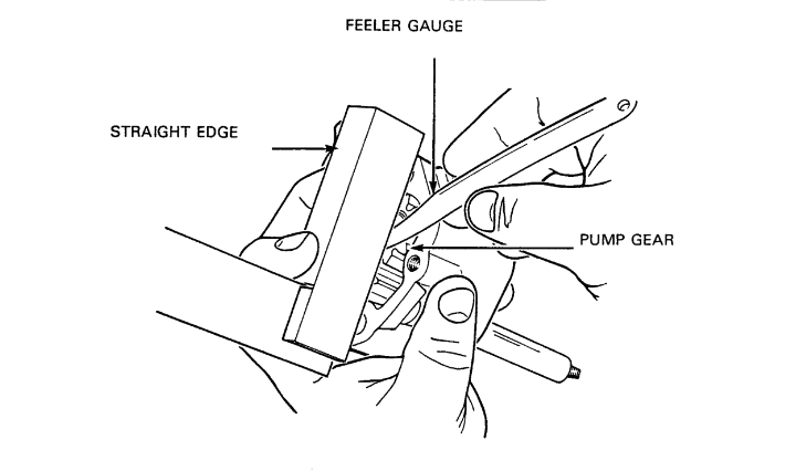
Figure 2-4-2 — Measurement of Oil Pump Gear Axial PlayClick image to enlarge.
- Using feeler gauges, measure the backlash clearance between the pump gears, see Figure 2-4-1. If the clearance is less than 0.05 mm or greater than 0.20 mm, replace either the pump or pump gears.
- Place a straight edge across the bottom of the oil pump body and, using feeler gauges, measure the clearance between the straight edge and gears to determine axial play, see Figure 2-4-2. If axial play is greater than 0.15 mm, replace the pump.
- Clean the strainer in the pick-up tube.
- Place the pick-up tube on the oil pump body, install the two cap screws and torque to 10 N•m (7 ft lb).
10.Installation — To install, proceed as follows:
- Insert the oil pump drive shaft into the engine block and, if necessary, turn the oil pump slightly so that the lug on the top of the oil pump drive shaft seats in the slot in the bottom of the distributor drive shaft.
- Install the two cap screws and flat washers and torque to 20 N•m (15 ft lb).
- Install the oil pan.
Oil Filter Housing
11.Removal — To remove, proceed as follows:
- Disconnect the electrical wire from the oil temperature sending unit on the filter housing.
- Using an oil filter wrench, remove the filter from the housing.
- Remove the oil temperature sending unit and gasket from the housing.
- Remove the three socket head screws and flat washers from the housing at the engine block and remove the housing and gasket.
12.Installation — To install, proceed as follows:
- Place a new gasket and the housing on the engine block and install the three socket head cap screws and flat washers. Torque to 20 N•m (15 ft lb).
- Coat the gasket of a new filter with clean oil and install the filter into the housing by hand. Tighten the filter until the gasket contacts the housing and then turn an additional 3/4 turn.
- Install the oil temperature sending unit and gasket on the housing and torque to 10 N•m (7 ft lb).
- Connect wire #34 to the sending unit terminal.
Section 5 — Engine Eletrical and Ignition System
General
Description of Starter
1.The starter is multipolar series wound with four brushes and aluminum field coils. A solenoid engages the starter drive pinion with the starter ring gear on the engine flywheel. To minimize wear and stress on the starter drive pinion and starter ring gear, the solenoid does not switch starting current to the starter motor until the drive pinion has fully engaged the ring gear. The drive pinion is mounted on an overrunning clutch to prevent damage to the starter motor as the result of overspeed when the drive pinion is driven by the engine. Solenoid replacement is the only field maintenance that should be considered. Other repairs to the starter involve disassembly of the starter using special tools and a press.
Description of Alternator
2.The Leece-Neville alternator is either 28 volts, 60 amps or 28 volts, 100 amps. Both alternators are self-current limiting with a fully adjustable solid state regulator with built-in radio frequency interference (RFI) suppression. There are sealed ball bearings with slip rings and brushes in a sealed housing mounted on the slip ring end housing. Six silicon diodes mounted in heat sinks convert alternating current from the delta wound stator into direct current. A capacitor connected between the heat sinks assists in suppressing transient voltage spikes which could damage the diodes. The brushes and voltage regulator are located in a waterproof housing and can be removed for replacement or inspection without dismantling the entire unit.
Description of Distributor
3.The distributor is basically a conventional distributor, but has a trigger wheel, pickup coil and stator assembly instead of points and a condenser. The pickup coil is made up of many turns of fine wire on a spool. The stator, which has four metal lugs and a permanent magnet, encloses the pickup coil. As the trigger wheel rotates, an alternating voltage is induced in the pickup coil. The reversing polarity of the alternating voltage provides the impulse which triggers the Transistorized Control Ignition Unit (TCI) to interrupt the primary current flow through the ignition coil.
Description of Speed Limiting Rotor
4.The distributor incorporates a speed limiter (governor) in the rotor. The limiter is operated by a plunger acting against spring pressure. The centrifugal force of the rotating rotor causes the plunger to move outward. When the plunger reaches its maximum travel, it touches a contact which causes the voltage to go to ground instead of a spark plug. Spring tension is set to govern engine speed between 6160 to 6540 rpm.
Description of Spark Plugs
5.There are four shielded, suppressed and waterproof spark plugs. Each plug has a gasket to seal it to the head and a rubber “O” ring around the body to prevent dirt from accumulatingat at the plug opening in the cylinder head.
Description of High Tension Cables
6.The high tension (HT) cables are shielded and waterproofed and the core is made of wire. The cables carry secondary voltage from the coil to the distributor and from the distributor to each spark plug.
Description of Coil
7.The coil is placed in the system between the TCI unit and the distributor. The coil has a suppressor attached to eliminate radio interference. The function of the coil is to transform low voltage primary current into high voltage secondary current to fire the spark plugs. The coil is a special type for this system and must not be replaced by any other type of coil.
Description of Ballast Resistor Assembly
8.The ballast resistor assembly, which consists of two resistors connected in series, reduces current flow to the coil when the engine is running. During starting, one resistor is by-passed, allowing increased current flow to the coil.
Description of Transistorized Control Ignition Unit (TCI)
9.The TCI unit is located in the ignition systern between the accessory switch, the coil and the distributor. The unit consists of a printed electrical circuit with transistors that are enclosed in a waterproof housing. The housing is finned to assist in cooling. It receives electrical impulses from the distributor pickup coil and then interrupts the primary current to the coil.
Description of Accessory Switch
10.When turned “ON”, the accessory switch allows voltage to go to the ignition circuit, the starter button, the warning lights and to all the accessories. When the switch is in the “OFF” position, there is still battery voltage at the alternator, starter, cooling fans, master light switch, horn, and the radio power box.
Component Removal and Installation
WARNING — Do not replace metric bolts with standard bolts. See WARNING page at the front of the manual.
Starter

Figure 2-5-1 — StarterClick image to enlarge.
11.Removal — To remove, see Figure 2-5-1 and proceed as follows:
- Disconnect the battery ground cable.
- Disconnect ignition wire #37B from starter terminal #15A and ignition starter button wire #74A from starter terminal #50.
- Disconnect battery master switch wire #6 and alternator cables #2 from starter terminal #30.
- Remove the socket head screw from the front starter bracket.
- Remove the nuts, washers and bolts from the top and side of the starter.
- Remove the nut and washer from the bolt at the bottom of the starter and push the bolt through the clutch housing.
- Remove the starter from the clutch housing.
12.Disassembly — To disassemble, proceed as follows:
- Disconnect the starter connector strap from the starter connector terminal on the solenoid.
- Remove the three flat head screws from the solenoid and starter housing.
- Turn and pull outward the drive pinion so that the solenoid plunger pull rod can be disengaged from the engaging fork and remove the solenoid.
- Remove the two nuts and washers and remove the starter support bracket.
- Remove the two slot head end cap screws and the end cap and gasket.
- Remove the “C” clip and spacer washer from the end of the armature shaft.
- Inspect the armature shaft for burrs near the “C” clip groove and using a file, remove all burrs.
- Remove the through bolts and end plate.
- Lift aside the brush springs and remove the positive brushes from the brush holder.

Figure 2-5-2 — Removal of Starter Stop Ring from Starter Snap RingClick image to enlarge.
- Remove the brush holder.
- Remove the field coil housing.
- Using a suitable tool, press the stop ring from the snap ring, see Figure 2-5-2, and remove both rings.
- Withdraw the armature from the starter drive housing.
- Position the starter drive housing at a 45° angle with the starter drive gear facing down and pull the drive gear from the housing.
CAUTION — Do not clean the armature, field coils, self-oiling end plate bushing, or drive pinion assembly with solvent. Solvent will damage the insulation of the armature and field coils and destroy the factory installed lubricants in the bushing and overrunning clutch of the drive-pinion.
- Wipe clean all parts of the starter motor and drive
13.Tests and Inspection — To test and inspect, proceed as follows:

Figure 2-5-3 — Removal of Bushing from Starter End PlateClick image to enlarge.

Figure 2-5-4 — Measurement of Starter Commutator Out-of-RoundClick image to enlarge.
- Inspect the bushing in the end plate. If the bushing is worn or damaged, press the bushing out and install a new bushing, using bushing installer VW 222a and a sleeve, see Figure 2-5-3.
- Measure the length of the brushes. If the brushes are less than 13 mm long, replace the brushes. To replace the negative (–) brushes, replace the entire brush holder. If new brushes are available, unsolder the brush wires from the brush holder. Install the new brushes, soldering on their wires in place of the original wires. To replace the positive (+) brushes, replace the field coils with new field coils that have brushes attached. Alternatively, if new brushes are available, crush the old brushes in a vise, and solder the new brushes onto the original brush wires. Because the field coils are aluminium, the brush wires are welded to the field coils and cannot be detached.
- Inspect the commutator for taper and uneven wear. Machine the commutator if taper or uneven wear is greater than 0.03 mm.
- Place the armature shaft on V-blocks and position a machinist's square against the commutator, see Figure 2-5-4. Hand-turn the commutator to measure the out-of-round. Machine the commutator if the out-of-round is greater than 0.03 mm.
- Inspect the drive pinion for chipped and burred teeth and ensure the overrunning clutch operates smoothly without noise or binding. Replace the drive pinion assembly if necessary.
- Remove all burrs from the snap ring and “C” clip grooves in the armature shaft.
- Test the armature for grounding:
- Place one end of an ohmmeter or battery-powered test lamp on the commutator and the other probe on the armature body or shaft. If the test lamp lights, or a reading is obtained on the ohmmeter, the windings are grounded.
- If a ground is indicated, clean the commutator with trichloroethylene and test again. If a ground is still indicated, replace the armature.
- Test the armature for open circuits:
- Inspect the commutator for burn marks which indicate an open circuit in the winding coil connected to one of the bars.
- Apply the test probe of an ohmmeter or battery-powered test lamp to the adjacent bars around the commutator. There should be continuity between all the bars. If an open circuit is indicated, replace or rewind the armature.
- Test the field coils for grounding:
- Test for continuity between the coils and the housing. Ensure the positive brushes are not touching the housing.
- If continuity is indicated, replace the field coils.
- Test the field coils for open circuits:
- Test for continuity between the starter connector strap and each of the positive brushes.
- If continuity is not indicated, there is an open circuit. Replace the field coils.
- Test the solenoid windings:
- Using two 12 volt batteries connected in series, energize the solenoid. The plunger should go into the housing. If necessary, start the plunger into the housing by hand.
- De-energize the solenoid. The plunger should come out of the housing immediately. If the plunger does not go in, or come out immediately, the windings are defective. Replace the solenoid.
14.Assembly — To assemble, proceed as follows:
- Apply a very light coat of molybdenum grease to the armature shaft.
- Position the starter drive housing at a 45° angle and insert the starter drive gear into the housing.
- Insert the armature shaft into the starter drive housing.
- Install the stop ring on the armature shaft.
- Install a new snap ring and with the stop ring supported on a press bed, press down on the armature shaft until the snap ring seats under the stop ring.
- Install the field coil housing and brush holder and attach the positive brushes to the brush holder.
- Install the end plate and through bolts and apply weatherproof sealer to the through bolts.
- Install the spacer washers and “C” clip on the armature shaft.
- Using a feeler gauge, measure the clearance between the “C” clip and spacer washers to determine the armature end play. End play should be 0.10 mm to 0.15 mm. If necessary, add or remove spacer washers until the end play is within the specified limits.
- Install the end cap gasket.
- Apply sealer to the two slot head end cap screws and install the end cap.
- Install the starter support bracket.
- Turn and pull outward the drive pinion so that the engaging fork moves far enough back to allow the solenoid plunger pull rod to engage the fork.
- Install the starter solenoid and apply weatherproof sealer to the three slot head screws and the end of the solenoid that fits into the starter housing.
- Connect the starter connector strap to the starter connector terminal on the solenoid.
15.Installation — To install, proceed as follows:
- Insert the end of the starter into the clutch housing ensuring the starter shaft engages in the bushing in the housing.
- Insert the bottom bolt through the clutch housing and into the starter. Install a nut and washer and torque to 25 N•m (18 ft lb).
- Insert the top and side bolts through the clutch housing and into the starter, install nuts and flat washers and torque to 25 N•m (18 ft lb).
- Install the socket head screw for the front support bracket and torque to 45 N•m (33 ft lb).
- Connect battery master switch cable #6 and alternator wires #2 to starter terminal #30.
- Connect ignition wire #37B to starter terminal #15a and starter button wire #74A to terminal #50.
- Connect the battery ground cable.
Starter Solenoid
16.Removal — To remove, see Starter Removal.
17.Installation — To install, see Starter Installation.
Alternator
18.General — The alternator mounting bushings and bolt should be periodically inspected and tightened, or replaced when necessary, to prevent vibration damage to the alternator (refer to Section 6).
19.Removal — To remove, proceed as follows:
- Disconnect the battery ground cable.
- Disconnect wire #1 from the alternator regulator with a 3/8 in. wrench.
- Disconnect wire #1D from the alternator regulator with a 1/4 in. wrench.
- Disconnect both positive wires #2 from the alternator with a 1/2 in. wrench.
- Disconnect negative wire #52 from the alternator with a 1/2 in. wrench.
- Remove the bolt, lock washer and flat washer from the adjusting arm and remove the drive belts.
- Swing the adjusting arm out of the way.
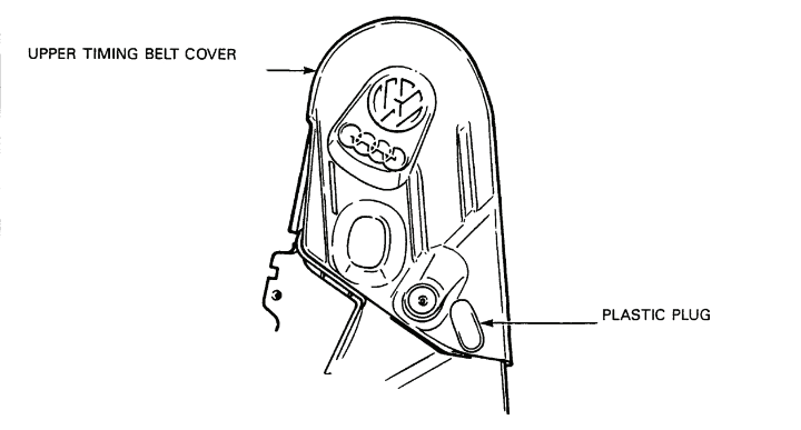
Figure 2-5-5 — Location of Plastic Plug in Timing Belt Upper CoverClick image to enlarge.
- Remove the plastic plug from the upper timing belt cover, see Figure 2-5-5, and insert a 6 mm hex head socket through the opening and onto the head of the alternator mounting bolt.
- Remove the nut from the mounting bolt.
- Support the alternator and withdraw the mounting bolt until it is free of the alternator.
- Remove the alternator from the mounting bracket.
20.Disassembly — Before disassembling the alternator, ensure that all alternator tests and adjustments, as described in Section 8, have been completed. To disassemble the alternator, see Figure 2-5-6 and proceed as follows:
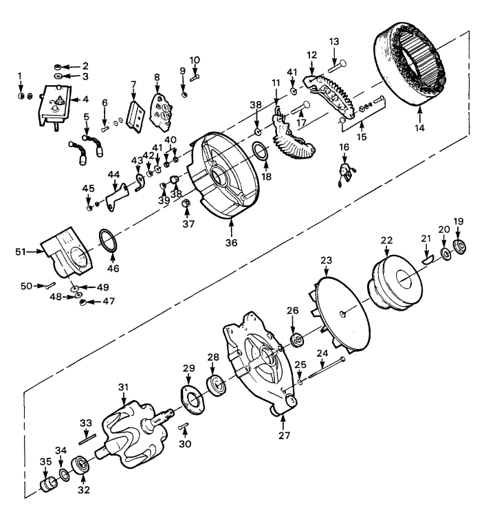
| 1. | Nut (1/4-20) |
| 2. | Nut |
| 3. | Lock Washer |
| 4. | Regulator |
| 5. | Brushes |
| 6. | Screw |
| 7. | Diode Trio |
| 8. | Terminal Board |
| 9. | Self-Locking Nut |
| 10. | Screw |
| 11. | Positive Rectifier |
| 12. | Negative Rectifier |
| 13. | Negative Terminal Output Bolt |
| 14. | Stator |
| 15. | Screw, Lock Washer Guard Washer, Insulating Washer |
| 16. | Capacitor |
| 17. | Positive Output Terminal Bolt |
| 18. | O-ring |
| 19. | Shaft Nut |
| 20. | Washer |
| 21. | Woodruff Key |
| 22. | Pulley |
| 23. | Fan |
| 24. | Through Bolt |
| 25. | Washer |
| 26. | Fan Spacer |
| 27. | Drive End Housing |
| 28. | Bearing |
| 29. | Bearing Retainer |
| 30. | Screw |
| 31. | Rotor |
| 32. | Drive End Housing Bearing |
| 33. | Slot Wedge |
| 34. | Insulation Washer |
| 35. | Slip Ring Assembly |
| 36. | Slip Ring End Housing |
| 37. | Self-Locking Nut |
| 38. | Insulating Bushing |
| 39. | Nut |
| 40. | Fibre Bushings |
| 41. | Guard Washers |
| 42. | Nut |
| 43. | Negative Jumper |
| 44. | Copper Jumper |
| 45. | Nut (1/4-20) |
| 46. | O-ring |
| 47. | Nut (6-32) |
| 48. | Lock Washer |
| 49. | Sealing Washer |
| 50. | Screw (8-32) |
| 51. | Holder |
Figure 2-5-6 — AlternatorClick image to enlarge.
NOTE — All nuts and bolts are standard and not metric.
- Hold the pulley (22) with a strap wrench and remove the shaft nut (19) and washer (20).
- Remove the pulley, fan (23), woodruff key (21), and fan spacer (26).
- Remove the nuts (1 and 45) from the negative alternator output terminal and the regulator terminal to free the copper jumper (44).
- Remove the three screws (6) and lock washers from the terminal board and remove the diode trio (7).
- Remove the nut (2) and lock washer (3) that secure the diode trio lead to the regulator (4).
- Remove the nuts (47), lock washers (48), negative jumper (43) and sealing washers (49) and remove the regulator and brushes.
- Remove the four screws (50) from the holder (51) and carefully remove the holder.
NOTE — Because of the application of Loctite to the holder screws, it may be necessary to apply heat to the screw heads with a large soldering iron. After heating the screws, remove them immediately.
- Mark the drive end housing (27) and slip ring end housing (36) to ensure correct assembly. Do not mark the stator (14).
- Remove the self-locking nuts (37), through bolts (24) and washers (25).
CAUTION — If the drive end housing binds on the stator, tap gently on the mounting ear with a fibre hammer to loosen. Ensure that the drive end housing separates from the stator and the stator remains attached to the slip ring end housing to avoid damage to the stator leads.
- Remove the rotor (31) and drive end housing assembly (27) from the stator (14) and slip ring end housing assembly (36).
- Remove the three nuts (9) that secure the stator leads to the terminal and remove the stator.
- Remove the nut (39) from the positive output terminal bolt (17) and remove the bolt and insulating bushings (38).
- Remove the nut from the negative output terminal bolt (13) and remove the bolt, two guard washers (41) and two fibre bushings (40).
- Remove the capacitor (16) connected between the positive rectifier (11) and the negative rectifier (12).
- Remove the two screws, lock washers, guard washers and insulating washers (15) that retain the lower end of the heat sinks.
- Remove the heat sinks and note the location of the insulating washers.
- Using a press or puller, remove the drive end housing and bearing assembly (28) from the rotor (31).
- Remove the four screws (30) and bearing retainer (29).
- Press the bearing (28) from the drive end housing.
21.Tests and Inspections — To test and inspect, proceed as follows:
- Carefully inspect all parts for wear, cracks, breakage or other mechanical defects and replace damaged parts with new ones as required.
- To test the positive and negative rectifier assemblies, proceed as follows:
NOTE — It is not necessary to remove the rectifier assemblies from the end housing or disconnect the rectifier leads in order to test the assemblies. If the assemblies are not removed, ensure the stator is removed. Ensure the diode trio has been removed from the terminal board and disconnect the capacitor connected between the lower end of the rectifier assemblies. Rectifier diodes are tested to ensure that the diodes pass current in one direction only. Diodes should be tested with a diode tester, but an analog ohmmeter or battery-powered test light can be used as a substitute.

Figure 2-5-7 — Rectifier Test PointsClick image to enlarge.
- Connect one lead of the test device to a diode lead and the other lead to the heat sink of that diode, see Figure 2-5-7. Note the reading.
- Reverse the test leads on that same diode and heat sink and note the reading. The ohmmeter or test light must indicate current flow in one test and no current flow in the other test. Replace the rectifier if necessary.
- Repeat steps (1) and (2) for each of the five remaining diodes and their corresponding heat sinks.
- Perform the Alternator Diode Trio Test (refer to Section 8).
NOTE — The capacitor that is connected across the heat sinks can be tested with either a capacitor tester or an analog ohmmeter.
- To test the capacitor, proceed as follows:
- Connect the positive and negative leads of a tester to each end of the capacitor leads. The test values should be 0.5 microfarad and 200 working volts DC.
- To test the capacitor using an analog ohmmeter, connect the positive and negative test leads to each of the capacitor leads. A high resistance should be indicated. If a low resistance is indicated, the capacitor is shorted or leaking and should be replaced.
- Install the regulator on a known serviceable alternator for testing. Replace the regulator if unserviceable.
- To test the rotor to determine whether it is grounded, proceed as follows:
- Connect one test lead of an ohmmeter to the rotor shaft.
- Touch the other test lead to each of the two slip rings. If a zero or close to zero reading is obtained, the rotor assembly is grounded and must be replaced.
- To test the rotor coil resistance, proceed as follows:
- Touch the negative and positive test leads of an ohmmeter to the two slip rings. Resistance should be 7.2 to 7.8 ohms.
- If resistance is not within the specified range, connect the test leads to the rotor coil soldered connections of the two slip rings. If the resistance is now within the specified range, resolder the rotor coil solder connections. If the resistance is still not within the specified range, replace the rotor assembly.
- To test the stator to determine whether it is grounded, proceed as follows:
- Inspect the stator visually. If the windings appear to be charred, or burned, or the insulation is missing and bare copper wire is visible, then the stator must be replaced.
- Using an ohmmeter, test between the stator frame and each of the stator leads for grounding. If the stator is grounded, replace it.
- Using an ohmmeter that is capable of reading 1/1000 of an ohm or a Wheatstone Bridge, check the stator phase resistance across pairs of terminals. Check the three possible combinations. If resistance is about the same for each one of the three phases, the stator phases are serviceable and may be reused providing the windings appear undamaged.
22.Assembly — To assemble, proceed as follows:
- Replace the slip ring and bearing:
NOTE — Place the new slip ring in a warm place so that it will press on easily without cracking.
- Using a soldering iron, remove the wire that connects the rotor coil to the outside slip ring.
- Bend the unsoldered wire until it is parallel to the shaft.
- Unsolder the wire from the inside slip ring.
- Using a gear puller or arbor press, remove the slip ring assembly and the insulation washer.
- Using a gear puller or an arbor press with fixture plates behind the bearing, remove the bearing from the rotor shaft. Do not lose the slot wedge.
- Install the slot wedge in the shaft slot and place the new bearing over the rotor shaft. Using a sleeve that contacts the inner bearing race, press the bearing on, ensuring the wedge remains in place.
- Place the new slip ring assembly on the rotor shaft. Ensure the wire slots align with the slot in the shaft.
CAUTION — When installing the slip ring assembly, use only enough pressure to prevent the insulation washer from turning.
- Press the slip ring assembly all the way onto the shoulder.
- Solder the rotor coil leads to the new slip ring assembly and test the resistance of the soldered connections.
- Place the rotor assembly on a lathe and take a slight cut from the circumference of the slip rings to ensure the rings are concentric with the rotor shaft. The concentricity of the slip rings to the bearing surfaces of the shaft must not exceed 0.002 inches total indicator reading.
- Using an arbor press, press the drive end housing bearing into the housing as far as possible.
- Install the bearing retainer with four screws.
- Place the slip ring end of the rotor shaft on an arbor press, ensuring that the slip rings are not damaged, and press the drive end housing onto the rotor shaft. Use a sleeve to ensure pressure is applied only to the inner race of the drive end bearing.
- Install the terminal board and two screws.
- Place the positive and negative rectifier assemblies in the slip ring end housing.
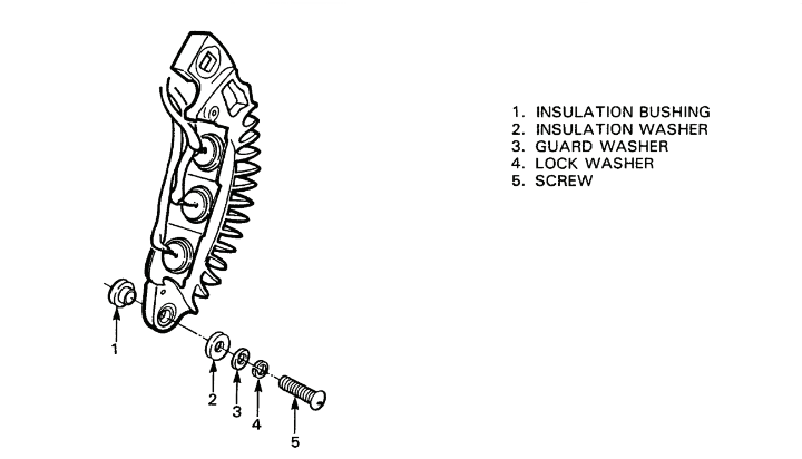
Figure 2-5-8 — Installation of Rectifier AssemblyClick image to enlarge.

Figure 2-5-9 — Positive Terminal AssemblyClick image to enlarge.

Figure 2-5-10 — Negative Terminal AssemblyClick image to enlarge.
- Install the insulation bushing (1) in the underside of the mounting hole and install the screw (5) with the lock washer (4), guard washer (3) and insulation washer (2) through the insulation bushing and mounting hole, see Figure 2-5-8. Do not tighten the screws at this time.
- Install an insulation bushing (1) on each side of the end housing (4). Install the positive terminal bolt (3) in the top of the positive rectifier assembly (2) and install a nut (5), see Figure 2-5-9. Tighten the nut and screw.
- Install the negative terminal bolt (3), with two fibre bushings (1) between the four guard washers (5) (two guard washers on each side of the end housing (4)), through the negative rectifier assembly (2) and end housing. Install a nut (6) on the bolt, see Figure 2-5-10. Tighten the nut and screw.
- Install the capacitor (16), see Figure 2-5-6 and capacitor terminals on the bottom of the rectifier assemblies with self-tapping screws. Remove the paint from around the holes before installing the leads.
- Place a rectifier terminal on each of the three terminal screws of the terminal board (8). When installing replacement rectifiers, remove paint from the terminals and install a positive and negative rectifier terminal on each terminal board screw.
- Install a new “O” ring (18) in the bearing bore of the 'slip ring end housing (36).
- Remove paint from the terminals and install the stator (14) on the slip ring end housing. Place the stator leads on the three terminal board screws. Ensure the assembly screw holes in the stator and the slip ring end housing are aligned.
- Ensure there is no interference between the rotor (31) and leads of the rectifiers (11 and 12) and stator.
- Secure the rectifier and stator leads with self-locking nuts.
- Support the slip ring end housing on flat plates in an arbor press, ensuring clearance is provided for the slip ring to pass through the housing, and press the slip ring end bearing into the slip ring end housing by pressing on the rotor shaft.
NOTE — Ensure the housing marks and the assembly screw holes are aligned in the slip ring end housing, stator and drive end housing.
- Install the three through bolts (24) and washers through the slip ring end housing, stator and drive end housing (27).
- Install the elastic lock nuts on the through bolts and torque to 622 N•cm (55 in lb).
- Ensure the “O” ring (46) is properly installed in the brush holder housing.
- Apply Loctite #242 to the threads and install the brush holder housing with the four #8 round head screws. Remove the tape from the housing.
- Insert the outer brush and spring assembly into the housing and compress the brush spring with a small screwdriver. While holding the spring compressed, insert a stiff piece of wire through the top hole in the rear of the housing so that the spring will be held in the compressed position.
- Install and compress the second brush and spring and push the wire farther into the brush housing to hold the second brush in the compressed position also.
- Carefully push the regulator (4) into the brush housing until the regulator contacts the brushes. Ensure that one of the screws goes through the negative jumper.
- Install a sealing washer, lock washer and nut on the positive output terminal. Hand tighten the nut while firmly holding the regulator in position.
- Install a sealing washer, jumper, lock washer and nut on the negative output terminal. Hand tighten the nut.
- Install the copper jumper (44) on the negative output terminal and the regulator terminal.
- Install a nut on each terminal and tighten.
CAUTION — To prevent damage to the regulator, ensure the wire that compresses the springs is removed before torquing the nuts.
- Remove the wire that compresses the springs and torque the nuts to 125 N•cm (11 in lb).
- Install the diode trio (7) with the three screws (6) and washers.
- Install the diode trio lead to the terminal on the regulator and install the lock washer and nut.
- Install a strip of tape over the two holes in the brush holder housing.
- Install the fan spacer (26) on the shaft and install the woodruff key (21), fan (23), pulley (22) and nut (19).
- Hold the pulley with a strap wrench and torque the nut to 65 N•m (48 ft lb).
- Test the alternator on a proper test block or by means of a test setup. After the battery has been connected, flash the field by connecting a jumper wire to the diode trio terminal pad on top of the regulator and momentarily touching the other end of the wire to the alternator positive (+) terminal.
23.Installation — To install, proceed as follows:
NOTE — When installing a new or reconditioned alternator, it may be necessary to remove the pulley from the used alternator and install the pulley on the new alternator before installing the alternator.
- Place the alternator on the mounting bracket and insert the mounting bolt through the mounting bracket.
- Install the nut on the bolt.
- Swing down the alternator adjusting arm and loosely install the adjusting bolt, lock and flat washers.
- Place the drive belts on the alternator pulley and adjust belt deflection to 15 mm.
- Tighten the mounting bolt, nut and adjusting bolt.
- Install the plastic plug in the upper timing belt cover.
- Connect negative wire #52 to the alternator negative terminal with a 1/2 in. wrench.
- Connect both positive wires #2 to the alternator positive terminal with a 1/2 in. wrench. Connect wire #1D to the alternator regulator terminal with a 1/4 in. wrench.
- Connect wire #1 to the regulator D+ terminal of the alternator, with a 3/8 in. wrench.
- Connect the battery ground cable.

Figure 2-5-11 — Flashing the Field of New or Rebuilt AlternatorClick image to enlarge.
NOTE — After installing a new or rebuilt alternator, momentarily flash the field to restore the residual magnetism which may have been weakened during handling and repair procedures.
- Connect a jumper cable to the diode trio terminal on the regulator and momentarily touch the other end of the cable to the positive terminal of the alternator, see Figure 2-5-11.
- Check and adjust the alternator voltage output (refer to Section 8).
Alternator Regulator
24.Removal — Before replacing the regulator, ensure that all alternator tests as described in Section 8 have been completed. To remove the regulator, proceed as follows:
- Remove the alternator.
- Remove the diode trio lead from the regulator terminal.
- Remove the three screws that secure the diode trio and remove the diode trio.
- Remove the two nuts at the bottom of the regulator and remove the negative jumper wire.
- Carefully pull the regulator from the holder and remove the regulator.
- Remove the brushes. If the brushes or springs are cracked, broken or burned, replace them. Measure the length of the brushes. If the brushes are less than 4.7 mm (3/16 in.) long, replace the brushes.
25.Installation — To install, proceed as follows:
- Insert the outer brush and spring assembly into the housing and compress the brush spring with a small screwdriver. While holding the spring compressed, insert a stiff piece of wire through the top hole in the rear of the housing so that the spring will be held in the compressed position.
- Install and compress the second brush and spring and push the wire further into the brush housing to hold the second brush in the compressed position also.
- Carefully push the regulator into the brush housing until the regulator contacts the brushes. Ensure a screw goes through the negative jumper.
- Install the lock washers and nuts and hand tighten.
CAUTION — To prevent damage to the regulator, ensure the wire that compresses the springs is removed before torquing the nuts.
- Remove the wire that compresses the springs and torque the nuts to 125 N•cm (11 in lb).
- Install the diode trio with the three screws and washers.
- Install the diode trio lead to the terminal on the regulator and install the nut and lockwasher.
- Install the jumper on the regulator 1/4 in. terminal. This jumper must be installed for RFI suppression.
- Install the alternator.
- Flash the field by connecting a jumper wire to the diode trio terminal terminal on the regulator and momentarily touching the other end of the wire to the alternator positive (+) terminal, see Figure 2-5-11.
Distributor
26.Removal — To remove, proceed as follows:
- Ensure the battery master switch is off.
- Disconnect the spark plug and coil HT cables from the distributor cap.

Figure 2-5-12 — DistributorClick image to enlarge.
- Disconnect the TCI connector at the base of the distributor cap, see Figure 2-5-12.
- Disconnect the two vacuum hoses from the vacuum unit.
- Disconnect the two ventilation hoses from the distributor housing.
- Remove the cap screw from the distributor lock collar, see Figure 2-5-12, and pull the collar from the distributor.
- Remove the distributor.
27.Disassembly — To disassemble, proceed as follows:
- Remove the fibre washer and rubber “O” ring from the bottom of the distributor housing.
- Loosen the three screws on the distributor cap and remove the cap.
- Remove the rubber seal from the groove in the top of the distributor housing.
- Remove the speed limiting rotor from the distributor shaft.
- Remove the two screws from the vacuum advance unit on the distributor and remove the unit.
- Remove the four screws from the TCI connector on the distributor and remove the connector and gasket.
- Remove the circlip above the trigger wheel.
CAUTION — To prevent damage to the trigger wheel, ensure the legs of the universal puller are far enough under the wheel to pull on the reinforced portions of the wheel.

Figure 2-5-13 — Removal of Distributor Trigger WheelClick image to enlarge.
- Using a universal puller, remove the trigger wheel from the distributor shaft, see Figure 2-5-13. Do not loose the small dowel pin located above the wheel.
- Remove the second circlip from the distributor shaft.
- Remove the three screws and lock washers from the stator assembly in the distributor housing and remove the assembly.
- Remove the dowel pin from the drive gear and press the gear from the shaft.
- Pull the shaft and centrifugal advance assembly from the housing.
- Press the upper and lower bushings from the housing.
- Remove the felt pad from the top of the shaft.
- Inspect the centrifugal advance weights for freedom of movement and spring tension by holding the lower shaft and should move out without binding and the springs should return the weights to the centre position when the upper shaft is released.
 | 1. | Springs |
| 2. | Upper Shaft | |
| 3. | Screw and Washers | |
| 4. | Felt | |
| 5. | Plastic Surface | |
| 6. | Shims | |
| 7. | Weights | |
| 8. | Fibre Washers | |
| 9. | Circlips | |
| 10. | Plate | |
| 11. | Lower Shaft | |
| 12. | Hinge Pins |
Figure 2-5-14 — Distributor Shaft and Centrifugal Advance AssemblyClick image to enlarge.
- If there is binding, see Figure 2-5-14, and proceed as follows:
- Remove the springs (1).
- Remove the circlips (9) from the hinge pins (12) and remove the weights (7) from the plate (10).
- Clean the weights, shaft and plate of excessive grease and dirt.
- Inspect the fibre washers (8) on the hinge pins for excessive wear.
- Inspect the nylon rub block on the weights for excessive wear.
- Place the weights on the hinge pins and inspect for excessive wear.
- Ensure the plastic surface (5) on the top and bottom of the spring pins is not worn.
- Remove the screw, lock and flat washers (3) from the upper shaft (2) and pull the upper shaft from the lower shaft (11).
- Remove the shims (6) from both shafts.
- Clean and inspect the shafts for wear and straightness. Replace the shafts, if necessary.
28.Assembly — To assemble, see Figure 2-5-14 and proceed as follows:
- Assemble the distributor shaft and centrifugal advance assembly:
- Apply a light coating of grease on the upper portion of the lower shaft (11) and the shaft plate (10).
- Install the shim (6).
- Place the upper shaft (2) on the lower shaft (11), ensuring the stops enter the elongated holes.
- Install the flat and lock washers and screw (3) in the upper shaft.
- Install the fibre washers (8) on the hinge pins (12).
- Install a weight (7) on each pin (12) and install a circlip (9) on each pin.
- Install the two springs (1).
- Saturate the felt (4) with engine oil and install in the top of the shaft.
- Press a new upper and lower bushing into the housing.
- Install the shaft and centrifugal advance assembly in the housing and press the drive gear onto the shaft, ensuring the gear is aligned with the dowel pin hole in the shaft.
- Drive a new dowel pin through the drive gear and shaft from the countersunk side of the gear.
- Install the vacuum advance unit on the distributor.
- Place the stator assembly on the shaft, ensuring the stator electrical contacts are not bent during installation, and carefully engage the stator pin with the vacuum unit.
- Install the stator assembly on the distributor.
- Install the TCI connector and gasket on the distributor with four screws and lock washers, ensuring the two contacts of the connector are at the top.
- Install a circlip in the groove above the stator assembly.
- Install the trigger wheel on the shaft, ensuring the small dowel pin is in the groove and install a circlip in the groove above the wheel.

Figure 2-5-15 — Gap Measurement Between Lugs of Trigger Wheel and StatorClick image to enlarge.
- Check the gap between the trigger wheel lugs and the stator lugs with the trigger wheel in four different positions, see Figure 2-5-15. The gap should be 0.25 mm (.010 in). If necessary adjust the gap by bending the trigger wheel or stator lugs.
- Install the speed limiting rotor on the shaft, ensuring the lug in the rotor fits into the slot in the shaft. Push the rotor down until it contacts the trigger wheel.
- Install the rubber “O” ring in the groove on top of the housing.
- Install the distributor cap on the distributor, and install the three screws.
- Install a new “O” ring and fibre washer on the bottom of the distributor housing.
29.Installation — To install, proceed as follows:
- Remove the timing plug from the flywheel housing.

Figure 2-5-16 — Flywheel Timing MarkClick image to enlarge.

Figure 2-5-17 — Camshaft Lobes Facing Up at Similar AnglesClick image to enlarge.
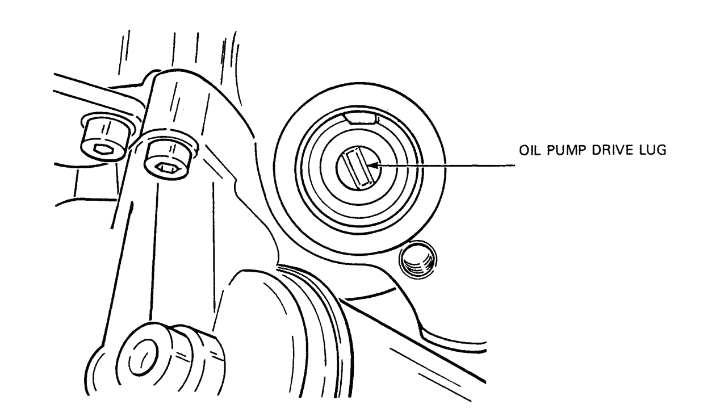
Figure 2-5-18 — Oil Pump Drive Lug AlignmentClick image to enlarge.
- Turn the crankshaft until the timing mark on the flywheel is aligned with the indicator, see Figure 2-5-16.
- Remove the oil filler cap from the valve cover and ensure both camshaft lobes of the #1 piston face upwards at similar angles. If the lobes do not face upward at the same angle, see Figure 2-5-17, rotate the crankshaft one complete revolution. Install the oil filler cap.
- Loosen the three screws from the distributor cap and remove the cap.
- Turn the rotor and shaft until the rotor contact faces toward the TCI connector socket.
- Ensure that the oil pump drive lug is correctly aligned so that the lug will fit into the slot in the bottom of the distributor shaft when the distributor shaft is inserted into the engine block, see Figure 2-5-18.
- With the TCI electrical connector facing straight back, insert the distributor shaft into the engine block until the oil pump drive lug fits into the slot in the bottom of the distributor shaft. Turn the distributor rotor shaft until the distributor gear meshes with the oil pump/distributor gear and the distributor seats against the block.
- Install the distributor lock collar and cap screw.
- Install the distributor cap.
- Install the spark plug HT cables to the corresponding terminals on the distributor cap. The spark plug terminal that is nearest the flywheel housing is the #1 spark plug cable terminal. The distributor rotation is clockwise and the firing order is 1, 3, 4, 2.
- Install the coil HT cable to the distributor cap.
- Install the TCI connector to the TCI connector socket.
- Install the ventilation hose from the air filter housing to the side of the distributor housing. Install the, ventilation hose from the brake servo hose to the base of the distributor housing.
- Install the vacuum line from the carburetor to the front of the vacuum advance unit and connect the vacuum line from the brake servo hose to the rear of the vacuum advance unit.
- Adjust the ignition timing (refer to Section 8).
- Tighten the distributor lock collar cap screw.
- Install the timing plug in the flywheel housing.
| Centrifugal Advance (Crankshaft Degrees and RPM) |
||
|---|---|---|
| Begins | rpm | 1,000 - 1,600 |
| Intermediate Range | rpm | 3,000 |
| degrees | 12 - 17° | |
| Ends | rpm | 4,200 |
| degrees | 23 - 27° | |
Figure 2-5-19 — Centrifugal Advance
- To check the centrifugal advance, proceed as follows:
- The distributor should be checked before and after overhaul to determine the scope of repair and satisfactory completion of repairs. A test machine should be used, if available, and the distributor tested as per manufacturer's instructions.
- If the distributor is checked on the vehicle using a stroboscopic lamp, see Figure 2-5-19 for centrifugal advance specifications.
| Vacuum Advance (Crankshaft Degrees) | |
|---|---|
| Begins | 260 - 340 mbar |
| (195 - 255 mmHg) | |
| Ends | 450 mbar |
| (340 mmHg) | |
| 11 - 15° | |
| Vacuum Retard (Crankshaft Degrees) | |
| Begins | 140 - 280 mbar |
| (105 - 210 mmHg) | |
| Ends | 320 - 420 mbar |
| (240 - 315 mmHg) | |
| 8 - 10° | |
Figure 2-5-20 — Vacuum Advance and Retard
- To check the vacuum advance/retard, proceed as follows:
- Run the engine at approximately 1,500 rpm and disconnect the vacuum advance hose from the front of the unit. The engine rpm should decrease.
- Install the vacuum advance hose and allow the engine to run at normal idle speed. Disconnect the vacuum retard hose from the rear of the unit. The engine rpm should increase. Install the vacuum retard hose.
- If proper test equipment is used, the vacuum unit should conform to the specifications in Figure 2-5-20.
Distributor Cap
30.Removal — To remove, proceed as follows:
- Ensure the battery master switch is off.
- Disconnect the spark plug and coil HT cables from the distributor cap.
- Loosen the three cap screws and washers and remove the cap.
31.Inspection — To inspect, proceed as follows:

Figure 2-5-21 — Distributor Cap Carbon BrushClick image to enlarge.
- Inspect the cap for cracks and carbon tracking and replace, if necessary.
- Clean the carbon from the cap contacts.
- Inspect the cap contacts for wear and replace the cap, if necessary.
- Inspect the carbon brush and spring for wear and replace, if necessary, see Figure 2-5-21.
- Ensure the carbon brush and spring move freely.
32.Installation — To install, proceed as follows:
- Place the cap on the distributor, ensuring the #1 terminal is over the TCI connector and install the three retaining screws.
- Install the spark plug and coil HT cables to the corresponding terminals on the cap. The firing order is 1, 3, 4, 2 in a clockwise direction.
Speed Limiting Rotor
33.Removal — To remove, proceed as follows:
- Ensure the battery master switch is off.
- Remove the distributor cap.
- Remove the rotor from the distributor shaft.

Figure 2-5-22 — Checking Spring Tension of Speed Limiting RotorClick image to enlarge.
34.Inspection — To inspect, proceed as follows:
- Remove carbon build-up from the rotor arm centre and outer contact.
- Using an ohmmeter set at Rx1K, measure the resistance between the rotor centre contact and the rotor arm outer contact. The resistance should be approximately 5k ohms.
- Ensure there is spring tension to the speed limiter, see Figure 2-5-22.
35.Installation — To install, proceed as follows:
- Install the rotor ensuring the lug fits in the slot in the distributor shaft. Push the rotor down until it contacts the trigger wheel.
- Install the distributor cap.
Distributor Induction Sender
36.Inspection — To inspect, remove the distributor cap and proceed as follows:
- Using a non-ferrous feeler gauge, measure the gap between the trigger wheel lugs and stator lugs, see Figure 2-5-15. The gap should be 0.25 mm (0.010 in). If necessary, adjust the gap by bending the trigger wheel or stator lugs. Check all gaps with the trigger wheel in various positions.
- Disconnect the cable between the distributor and the TCI control unit.
- Using an ohmmeter set at Rx1K, measure the resistance at the disconnected TCI wire connector plug. If the resistance is not between 0.990 and 1.210k ohms, replace the pickup coil.
- Install the distributor cap.
Spark Plugs
37.Removal — To remove, proceed as follows:
- Ensure the battery master switch is off.
- Disconnect the HT cables from the spark plugs.
- Remove the spark plugs.
38.Installation — To install, proceed as follows:
- Using a spark plug feeler gauge, gap the new spark plugs. The spark plug gap should be 0.7 to 0.8 mm (.028 to .032 in).
- Ensure there is a gasket on each spark plug and a rubber “O” ring around the body.
- Install the spark plugs and torque to 30 N•m (22 ft lb).
CAUTION — Do not overtighten the cables; snug the cables only. If the cables are overtightened, the spark plugs will unscrew with the cables when the cables are disconnected the next time.
- Apply a light film of silicone grease to the cable threads and connect the HT cables to the corresponding spark plugs. The firing order is 1, 3, 4, 2 in a clockwise direction on the distributor cap.
Coil and Spark Plug High Tension Cables
39.Removal — To remove, proceed as follows:
- Ensure the battery master switch is off.
- Disconnect the HT cables from the four spark plugs.
- Disconnect the spark plug HT and coil HT cables from the distributor cap.
- Remove the spark plug HT cables from the cable brackets.
- Disconnect the coil HT cable from the coil.
40.Installation — To install, proceed as follows:
- Test the new cables for continuity and ensure the Bakelite tip at the ends of each cable is not broken.
- Apply silicone grease to the cable threads and install the coil and spark plug HT cables to the corresponding terminals on the distributor cap but do not tighten.
- Install the spark plug HT cables to the corresponding spark plugs but do not tighten.
- Install the spark plug HT cables into the cable brackets.
- Install the coil HT cable to the coil.
- Tighten all HT cable connections.
Coil

Figure 2-5-23 — CoilClick image to enlarge.
41.Removal — To remove, see Figure 2-5-23 and proceed as follows:
- Ensure the battery master switch is off.
- Remove the HT cable from the coil
CAUTION — To prevent damage, do not allow the TCI unit cable and suppressor unit cable to twist during removal.
- Remove the TCI and the suppressor unit cables from the top of the coil.
- Remove the wire from the bottom of the suppressor unit.
- Remove the cap screws, coil and suppressor.
42.Installation — To install, see Figure 2-5-23 and proceed as follows:
- Position the suppressor on the coil mounting bracket nearest the radiator and insert a cap screw through the suppressor and coil brackets.
- Position the mounting bracket on the fender and install the cap screws.
- Install the wire #37 to the bottom of the suppressor.
- Install the HT cable to the top centre of the coil.
- Install the TCI cable to the #1 (–) terminal of the coil and the suppressor cable to the radiator side #15 (+) terminal.
Ballast Resistors
43.Removal — To remove, proceed as follows:
- Ensure the battery master switch is off.
- Remove the four screws from the wire leads on the resistors and remove the wires.
- Remove the two sheet metal screws from the resistors and bracket and remove the resistors.
44.Installation — To install, proceed as follows:
- Place the resistors on the bracket and install the two sheet metal screws.
- Install the wire leads on the terminals ensuring the jump wire leads are on the top terminals and install the four screws.
TCI Unit
45.General — The TCI unit is mounted on the left side of the firewall and connected to the ignition coil, the distributor and the wiring harness from the accessory switch.
46.Removal — To remove, proceed as follows:
- Ensure the battery master switch is off.
CAUTION — To prevent damage, ensure the TCI cables do not twist when disconnecting the electrical connections from the TCI unit.
- Unscrew the electrical connections from the bottom of the TCI unit.
- Remove the two screws and flat washers from the TCI unit on the firewall and remove the TCI unit.
47.Installation — To install, proceed as follows:
- Position the TCI unit on the firewall and install the two screws and flat washers.
- Install the electrical connectors to the correct terminals. Install the cable from the distributor to the right terminal, the cable from the #1 (–) terminal of the coil to the centre terminal and the cable from the wiring harness from the accessory switch to the left terminal.
Section 6 — Engine Mechanical
General
Engine Description
1.The engine has four cylinders and is watercooled. It has a bore and stroke of 79.5 x 86.4 mm (3.13 x 3.4 in) giving a total displacement of 1.7 litres or 1,714 cu cm (105 cu in). It has a compression ratio of 8.2:1 with a power output of 55 kw (74 HP) at 5,000 RPM and a torque output of 135 N•m (100 ft lb) at 2,800 rpm. It I ncorporates a centrifugal type governor in the distributor rotor which limits engine rpm to a maximum of between 6,160 to 6,540 rpm. It is designed to use regular leaded gasoline.
2.The engine is fastened to the bell housing on the transaxle and both are attached to the frame by bonded rubber mountings.
3.Engine Block — The engine block is made of cast iron. For added strength, the sides of the crankcase extend below the main bearing center line. The cylinders are integral with the block and completely exposed on all sides to the coolant in the coolant jacket. The cylinders can be bored to accept oversized pistons.
4.Crankshaft and Bearings — The fully counterweighted crankshaft revolves in five splitshell main bearings. The centre bearing shells are flanged to take crankshaft end thrust. Seals, pressed into lightweight alloy seal carriers, are used at both ends of the crankshaft to prevent oil leakage.
5.Flywheel — The flywheel is bolted to the rear of the crankshaft. It provides the mounting surface for the clutch pressure plate and clutch disc and is equipped with a ring gear for the starter drive. One crankshaft mounting hole is unequally spaced to ensure proper mounting.
6.Connecting Rods and Pistons — The connecting rods are forged steel. Split-shell bearings are used at the crankshaft and lead-bronze coated steel bushings at the piston pins. The bearings and rods are drilled to provide lubrication to the piston pins. The pistons are made of cast aluminum and have two compression and one oil ring. Each piston has its diameter, weight class, and direction of installation stamped on its crown, and is mounted to the connecting rod with a full-floating pin retained by circlips.
7.Cylinder Head — The cylinder head is an aluminum alloy casting with integral bearing surfaces for the overhead camshaft. Pressed-in valve guides are used but the bores for the bucket-type cam followers are machined directly into the cylinder head material. Machined steel valve seats are pressed into the head. The head can be resurfaced within specifications to remove distortion and is secured to the cylinder block with 12 point socket head M10 bolts.
8.Valve Train — The single, overhead camshaft is mounted to the cylinder head by five bearing caps. The cam lobes, two per cylinder, operate the intake and exhaust valves by pressing on hardened steel valve adjusting shims that are placed in recesses atop the bucket-type cam followers. The camshaft is driven by a sprocket at the front of the engine through an adjustable timing belt driven by the crankshaft sprocket. The timing belt is enclosed by an upper and lower cover. Intake and exhaust valves have dual valve springs, spring seats, retainers, seals and keepers. The camshaft and valves are enclosed by a valve cover over the head.
9.Intermediate Shaft — The intermediate shaft, which is also sprocket driven by the timing belt from the crankshaft sprocket, runs from front to rear on the left side. It is supported by two bearings and provides a drive for the distributor. A lobe on the intermediate shaft can be used to drive a mechanical fuel pump if required (a mechanical fuel pump is not installed on the engine).
Component Removal and Installation
WARNING — Do not replace metric bolts with standard bolts. See the WARNING page at the front of the manual.
Engine
10.Removal — To remove, proceed as follows:
- Disconnect the battery ground cable.
- Raise the hood.
- Drain the cooling system (refer to Section 8).
- Remove the front bumper (refer to Part 6, Section 2).
- Remove the following cooling system components:
- Remove the radiator and fan assembly (refer to Section 3).
- Remove the expansion reservoir (refer to Section 3).
- Remove the coolant hose “T” junction from the heater hose leading to the firewall.
- Remove the return heater hose from the rear of the cylinder head and cap the opening.
- Remove the radiator grille bolts and lift the radiator grille from the engine compartment.
- Remove the bolts and lock washers from the radiator mounting bracket and remove the bracket.
- Remove the two cap screws, flat and lock washers, and the radiator guard.
- Remove the crossmember.
- Complete the following carburetor disconnections:
- Remove the carburetor intake hose from the carburetor.
- Remove the carburetor intake hose at the air cleaner outlet.
- Remove the breather hose at the valve cover.
- Loosen the screw from the choke cable casing at the carburetor and the screw from the choke cable and control lever.
- Pull the choke cable, casing and hose away from the carburetor.
- Remove the fuel line to the carburetor fuel inlet.
- Remove the two fuel by-pass reservoir mounting bolts and move the reservoir and in-line fuel filter out of the way.
- Remove the two clips on both sides of the rubber grommet on the accelerator cable.
- Remove the clip from the cam of the throttle linkage, disconnect the cable from the cam and pull the accelerator cable out of the bracket.

Figure 2-6-1 — Carburetor Air/Fuel Cutoff ValveClick image to enlarge.
- Remove the wire from the air/fuel cutoff valve, see Figure 2-6-1.
- Remove the vacuum advance line from the carburetor.
- Complete the following vacuum line disconnections:
- Disconnect the distributor vacuum retard line from the brake servo vacuum line at the “T” junction.
- Disconnect the distributor ventilation hose from the brake servo vacuum line at the “T” junction.
- Remove the brake servo vacuum line from the intake manifold.
- Complete the following electrical disconnections:
- Remove the two alternator terminal nuts from the rear of the alternator.
- Disconnect the wire leading to the oil temperature sending unit at the oil filter housing.
- Disconnect the TCI connector from the base of the distributor.
- Remove the two wires for the oil pressure sending unit at the rear of the cylinder head.
- Disconnect the wire for the coolant temperature gauge sending unit.
- Disconnect the wire for the temperature warning light sending unit.
- Disconnect the coil HT cable at the coil.
- Remove the block heater cord from the clip on the fender panel.
- Disconnect the engine ground strap from the clutch housing.
j. Complete the following transaxle disconnections:
- Remove the clutch housing breather hose, and cap the opening.

Figure 2-6-2 — Clutch Cable at Engine Mounting BracketClick image to enlarge.

Figure 2-6-3 — Transaxle Support VW785/1B InstalledClick image to enlarge.

Figure 2-6-4 — Engine Mounting Bolts and ComponentsClick image to enlarge.

Figure 2-6-5 — Lifting Sling Secured to EngineClick image to enlarge.
- Remove the clutch cable from the engine mounting bracket, see Figure 2-6-2.
- Disconnect the clutch cable from the hook on the end of the clutch lever.
- Install transaxle support VW 785/1B, see Figure 2-6-3.
- Remove the two cap screws and lock washers from the bottom of the clutch housing and the three cap screws and lock washers from the top of the clutch housing.
NOTE — The top left clutch housing cap screw also secures the heater hose rod to the housing. Remove the rod after removing the cap screw.
- Remove the bolt, nut and washer from the clutch housing, below the starter.
- Remove the starter from the engine (refer to Section 5).
- Remove the six nuts from the exhaust pipe at the manifold.
- Remove the muffler front hanger bolt. Pull the exhaust pipe away from the manifold and remove the gasket.
- Ensure the wheels are blocked and the hand brake applied.
- Remove the two engine mounting bolts, nuts, thick washers, lower support pads and washers, see Figure 2-6-4.
- Attach lifting sling 2024A to the front and rear lifting eyes of the engine, see Figure 2-6-5.
- Lift the engine slightly and pull toward the front of the vehicle until the clutch is free of the transaxle input shaft.
- Remove the engine from the engine compartment.
- Remove the upper support pads and washers from both engine mounts.
11.Installation — To install, proceed as follows:
CAUTION — To prevent vehicle damage when guiding the engine into the engine compartment, ensure the exhaust manifold does not bind against the exhaust pipe.
- Install a new gasket on the clutch housing and coat liberally with RTV.
- Ensure the wheels are blocked and the hand brake applied.
- Attach lifting sling 2024A to the front and rear lifting eyes of the engine, and lift the engine high enough to clear the front engine mounts.
- Guide the engine into the engine compartment until the clutch plate contacts the transaxle input shaft.
- Turn the crankshaft pulley securing nut until the splines of the clutch plate and transaxle input shaft will mesh and then push the engine against the clutch housing.
- Install the three clutch housing cap screws and lock washers at the top of the housing.
NOTE — The top left clutch housing cap screw also secures the heater hose rod to the clutch housing. Install the heater hose rod to the housing when installing the cap screw.
- Install the clutch housing bolt, washer and nut on the right side of the housing below the starter.
- Install the engine ground strap to the clutch housing below the breather hose pipe with a cap screw and washer.
- Install the two clutch housing cap screws at the bottom of the housing.
- Place an upper support pad and washer on both engine mounts.
- Insert a lower support pad, washer and mounting bolt into the bottom of the left engine mount and lower the engine until the mounting bolt is through the bracket.
- Insert a lower support pad, washer and mounting bolt into the bottom of the right engine mount and lower the engine until the mounting bolt is through the right support.
- Install a thick washer and nut on each mounting bolt.
- Lower the engine and remove the lifting sling.
- Torque the engine mounting bolts to 45 N•m (33 ft lb).
- Torque the four clutch housing cap screws and the bolt at the top and sides of the housing to 55 N•m (41 ft lb).
- Torque the two cap screws at the bottom of the housing to 25 N•m (18 ft lb).
- Remove the transaxle support.
- Install the starter (refer to Section 5).
- Raise the muffler and install the front hanger bolt.
- Place a new gasket on the end of the exhaust pipe, fit the pipe to the exhaust manifold and secure with six nuts.
- Complete the following transaxle connections:
- Remove the cap from the clutch housing breather opening.
- Install the clutch housing breather hose to the housing.
- Attach the end of the clutch cable to the hook on the end of the clutch lever and insert the cable into the engine mounting bracket.
- Complete the following electrical connections:
- Connect the coil high tension cable to the terminal on the distributor cap.
- Connect wire #33 to the coolant temperature sending unit terminal and install the nut and wire #32 on the coolant temperature warning light sending unit.
- Connect wires #35 and #36 to the oil pressure sending unit terminal and install two nuts.
- Connect wire #34 to the oil temperature sending unit and install a retaining nut.
- Connect the ICI connector to the base of the distributor.
- Connect negative (—) wire #52 to the alternator negative (—) terminal.
- Connect positive (+) wire #2 to the alternator positive (+) terminal.
- Connect wire #1 to the regulator D+ terminal of the alternator.
- Connect wire #1D to the regulator terminal of the alternator.
NOTE — The manufacturer recommends that if a new, or rebuilt alternator is installed, momentarily flash the field. Connect one end of a jumper cable to the diode trio terminal on the regulator and touch the other end of the jumper cable to the positive (+) terminal of the alternator for a few seconds, see Figure 2-5-11.
- Install the block heater cord in the clip on the fender panel.
- Complete the following connections:
- Insert the rubber grommet and the accelerator cable into the cable bracket. Place the cable tip in the cam of the throttle linkage and install the clip on the cam.
- Adjust the accelerator cable until there is a maximum of 1 mm clearance between the throttle sector plate and the stop with the accelerator pedal in the full-throttle position and install a spring clip on each side of the cable at the bracket.
- Check the clearance between the throttle sector plate and stop a second time with the accelerator pedal in the full-throttle position. Adjust the clearance, if necessary.
- Connect the electrical lead to the air/fuel cutoff valve terminal.
- Ensure the choke control knob is pushed in and insert the casing of the choke cable and hose into the bracket until the casing and hose protrude slightly past the bracket to ensure the clamp will hold the casing and tighten the screw. Ensure the choke opens and closes completely.
- Insert the choke cable through the control lever at the carburetor and, with the choke fully open and the choke cable fully in the control lever, secure the cable to the control lever with a screw.
- Insert the vacuum advance line into the rubber hose at the carburetor.
- Install the carburetor air intake hose.
- Position the fuel by-pass reservoir on the right fender panel and install the two bolts.
- Install the fuel line to the carburetor.
- Install the other end of the carburetor air intake hose to the air cleaner assembly.
- Install the breather hose to the valve cover.
- Install the brake servo vacuum line to the intake manifold.
- Install the distributor vacuum retard line to the brake servo vacuum line at the “T” junction which is closest to the intake manifold.
- Install the distributor ventilation hose to the brake servo vacuum line at its “T” junction.
- Install the front bumper (refer to Part 6, Section 2).
- Install the following cooling system components:
- Install the crossmember with two cap screws, flat and lock washers.
- Install the radiator guard to the front crossmember with two cap screws, flat and lock washers.
- Install the radiator mounting bracket with four slotted cap screws, flat and lock washers.
- Slide the radiator grille into place behind the headlight cover plates and install the four cap screws and flat washers.
- Install the radiator and fan assembly (refer to Section 3).
- Install the expansion reservoir (refer to Section 3).
- Install the return heater hose to the coolant hose “T” junction.
- Remove the cap from the rear of the cylinder head, and install the remaining heater hose.
- Connect the battery ground cable.
- Fill the cooling system (refer to Section 8).
NOTE — Before installing the engine protection plate as part of the procedure for filling the cooling system, ensure the system is not leaking.
- Start the engine. Check for leaks and make adjustments as required.
- Install the engine protection plate.
- Lower the hood.
Valve Cover
12.Removal — To remove, proceed as follows:
- Remove the vacuum advance line from the carburetor.
- Remove the brake servo vacuum hose from the intake manifold.
- Remove the retaining clip from each side of the rubber grommet on the accelerator cable at the cable mounting bracket.
- Remove the clip from the tip of the accelerator cable at the cam of the throttle linkage.
- Disconnect the accelerator cable from the cam plate, and pull the cable out of the bracket.
- Remove the valve cover breather hose.
- Remove the eight valve cover nuts.
- Remove the flat washer from both front studs.
- Remove the accelerator cable support bracket and two spark plug cable brackets and washers from the left side of the valve cover.
- Remove the plug nut from the middle of the timing belt upper cover and remove the cover.
- Remove the reinforcement bars from both sides of the valve cover.
- Remove the valve cover.
- Remove the gasket from the valve cover.
- Remove the rubber half seal from the front camshaft bearing cap.
- Inspect the valve cover studs for damage and replace, if necessary.
- Remove the valve cover rubber plug at the rear of the cylinder head.
13.Installation — To install, proceed as follows:
- Ensure the gasket surface of the cylinder head is clean.
- Install a new rubber half seal on the front camshaft bearing cap.
- Install a new rubber plug at the rear of the cylinder head.
- Install a new valve cover gasket on the cylinder head.

Figure 2-6-6 — Valve Cover Reinforcement BarsClick image to enlarge.
- Install the valve cover and reinforcement bars, ensuring the flat side of the bar faces toward the cover and the pointed end of the bar points toward the rear of the vehicle, see Figure 2-6-6.
- Install the timing belt upper cover and plug nut.
- Place the two spark plug cable brackets, washers and accelerator cable support bracket on the left centre studs.
- Install a flat washer on both front studs.
- Install the eight nuts and torque to 10 N•m (7 ft lb).
- Install the breather hose on the valve cover.
- Install the accelerator cable and check adjustment (refer to Section 1).
- Install the vacuum line from the vacuum advance unit to the carburetor.
- Install the brake servo vacuum hose on the intake manifold.
Camshaft
14.Removal — To remove, proceed as follows:
- Remove the timing belt upper cover and valve cover.

Figure 2-6-7 — Camshaft Sprocket Timing MarkClick image to enlarge.

Figure 2-6-8 — Timing Belt TensionerClick image to enlarge.

CAUTION — The bearing caps are off center. If a cap is installed incorrectly, the cap or cylinder head will crack during tightening.
Figure 2-6-9 — Camshaft Bearing Cap InstallationClick image to enlarge.
- Turn the crankshaft until the timing mark on the rear of the camshaft sprocket is even with the top edge of the rear timing belt plate, see Figure 2-6-7, and the timing mark on the flywheel is even with the mark on the clutch housing, see Figure 2-5-16.
- Loosen the timing belt tensioner locking nut, see Figure 2-6-8.
- Turn the timing belt tensioner counterclockwise to reduce the timing belt tension.
- Slide the timing belt from the camshaft sprocket.
- Remove the camshaft sprocket cap screw and flat washer.
- Pull the sprocket from the end of the camshaft and remove the woodruff key from the camshaft.
- Block the oil return openings in the cylinder head with cloth to prevent washers and nuts from falling into the oil passages.
- Remove the nuts and flat washers from camshaft bearing caps one, three and five and set the caps aside, in order, so that each bearing cap will be reinstalled in the same place, see Figure 2-6-9.
- To avoid camshaft distortion, loosen, a little at a time, the four nuts on camshaft bearing caps two and four until the tension is released. Remove the nuts, flat washers and bearing caps, and set the bearing caps aside, in order.
- Remove the camshaft from the cylinder head and slide the seal from the front end of the camshaft.
15.Inspection — To inspect, proceed as follows:
- Inspect the toes and flats of the camshaft lobes for wear and grooving. Wear and grooves are an indication of engine oil contamination.
- Inspect the camshaft bearing surfaces for grooves and replace the camshaft, if necessary.
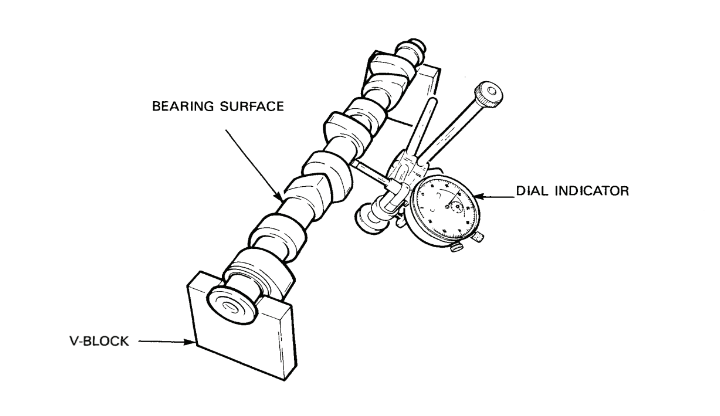
Figure 2-6-10 — Measurement of Camshaft Run-OutClick image to enlarge.
- Place the camshaft bearing surfaces one and five on V-blocks or inverted bearing caps and, using a dial indicator, measure the run-out of the camshaft, see Figure 2-6-10. Replace the camshaft, if the run-out is greater than 0.01 mm.
- To measure the camshaft axial clearance, proceed as follows:
- Remove the shims and buckettype cam followers from the cylinder head and set aside, in order, so that each will be reinstalled in the same location.
- Install the camshaft and bearing caps one and five and install washers and nuts. To ensure the bearing caps are correctly positioned, see Figure 2-6-9.
- Tap either end of the camshaft so that all the clearance is at one end.

Figure 2-6-11 — Measurement of Camshaft Axial ClearanceClick image to enlarge.
- Place a dial indicator, set at zero, at the end of the camshaft with all the clearance and tap the opposite end of the camshaft, see Figure 2-6-11, to eliminate the clearance at the dial indicator end of the camshaft. If the axial clearance is greater than 0.15 mm, install a new camshaft and measure axial clearance. If the clearance is still unacceptable, replace the cylinder head.
- To measure camshaft bearing clearance, proceed as follows:
- Install the camshaft and place a small piece of 0.25 - 0.76 mm Plastigage on all five bearing surfaces.
- Install the bearing caps, washers, and nuts in their correct positions, see Figure 2-6-9, and torque to 20 N•m (15 ft lb). Do not turn the camshaft.
- Remove the bearing caps.

Figure 2-6-12 — Measurement of Camshaft Bearing ClearanceClick image to enlarge.
- Using the Plastigage package, measure the Plastigage squash, see Figure 2-6-12. The bearing clearance should be 0.02 mm to 0.05 mm. Replace the camshaft if the bearing clearance is greater than 0.05 mm. If the clearance is not within the specifications after replacing the camshaft, replace the cylinder head.
16.Installation — To install, proceed as follows:
- Install the bucket-type cam followers and valve adjusting shims and lubricate.
- Clean and lubricate the camshaft bearing cap surfaces of the cylinder head.
- Ensure all camshaft lubricating holes in the cylinder head are open.
- Lubricate the lip of a new seal and install the seal on the front end of the camshaft with the lip facing toward the rear.
- e. Install the camshaft.
- Install bearing caps two and four over the corresponding camshaft bearing surfaces. The bearing caps are offset. Ensure the bearing caps are correctly positioned, see Figure 2-6-9.
- Install flat washers and nuts on bearing caps two and four and tighten each nut a little at a time. Torque to 20 N•m (15 ft lb).

Figure 2-6-13 — Checking Timing Belt TensionClick image to enlarge.
- Install bearing caps one, three and five over the corresponding camshaft bearing surfaces, ensuring the bearing caps are correctly positioned.
- Install washers and nuts on bearing caps one, three and five and torque to 20 N•m (15 ft lb).
- Install the camshaft sprocket and torque to 80 N•m (59 ft lb).
- Check the valve tappet clearance and adjust if necessary (refer to Section 8).
- Remove the cloth from the oil return openings and time the engine as detailed in Section 8.
Cylinder Head
17.Removal — To remove, proceed as follows:
- Disconnect the choke and accelerator cables from the carburetor.
- Disconnect the vacuum line and fuel line from the carburetor.
- Disconnect the electrical wires from the carburetor air/fuel cutoff valve and at the oil pressure and coolant temperature sending units.
- Drain the coolant (refer to Section 8).
- Remove the air intake hose from the carburetor and air cleaner assembly and remove the breather hose from the valve cover.
- Disconnect the inlet fuel line at carburetor.
- Remove the fuel by-pass reservoir from the right fender panel and move the reservoir and in-line fuel filter out of the way.
- Remove the six nuts securing the exhaust pipe to the manifold and remove the gasket.
- Disconnect the HT cables from the spark plugs and remove the two spark plug cable brackets from the valve cover.
- Loosen the three machine screws from the distributor cap and remove the cap and HT cables. Cover the distributor with a cloth.
- Disconnect the two heater hoses from the rear of the cylinder head.
- Disconnect the top radiator hose and the thermostat by-pass hose from the connector on the left side of the cylinder head.
- Remove the timing belt upper cover.
- Remove the valve cover.
- Slacken the tensioner and remove the timing belt.
- Remove the camshaft sprocket bolt and flat washer and slide the sprocket from the camshaft.
- Loosen the alternator adjusting arm bolt.
- Remove the alternator adjusting arm cap screw and swing the bracket away from the cylinder head.
- Remove the intake manifold and gasket from the cylinder head (refer to Section 2).
- Remove the exhaust manifold and gaskets from the cylinder head (refer to Section 2).
CAUTION — To prevent distortion to the cylinder head, ensure the engine is cool before loosening the cylinder head securing bolts.

Figure 2-6-14 — Cylinder Head Bolt Torquing SequenceClick image to enlarge.

Figure 2-6-15 — Engine Block Distortion InspectionClick image to enlarge.
- Working alternately from the front and rear of the cylinder head and towards the center, loosen a little at a time, the cylinder head bolts in the reverse sequence to that shown in Figure 2-6-14. Remove the bolts and flat washers.
- Lift the cylinder head from the engine block. If the head will not move, insert the handle of a hammer into an exhaust port and pry the head loose.
- Remove the head gasket and, using either a plastic scraper or solvent, remove the pieces of gasket that are stuck to the cylinder head and engine block. Do not use a metal scraper or wire brush.
- Using a straight edge and feeler gauge, inspect the sealing surface of the engine block for distortion from corner to corner, end to end and side to side, see Figure 2-6-15. If the distortion is greater than 0.10 mm, the engine block must be resurfaced. The maximum amount that can be cut from an engine block is 0.25 mm.
- Inspect the pistons and cylinder walls for scoring.
- Cover the top of the engine block.
18.Installation — To install, proceed as follows:
- Remove the cover from the engine block. Ensure the sealing surface, pistons and cylinders are clean and apply engine oil to the cylinder walls.
- Place a new head gasket on the engine block with the word “OBEN” or “TOP” towards the cylinder head.
- Ensure the sealing surface of the cylinder head is clean and place the head on the engine block.
- Apply an anti-seize compound to the ten cylinder head bolts to prevent seizure to the aluminium head and install the bolts and flat washers.
- Tighten the cylinder head bolts following the sequence shown in Figure 2-6-14, and torque the bolts to 30 N•m (22 ft lb).
- Torque the cylinder head bolts to 58 N•m (43 ft lb) following the sequence described in step e.
- Torque the cylinder head bolts to 75 N•m (55 ft lb) following the sequence described in step e.
- After torquing all cylinder head bolts, turn each bolt a further quarter turn following the sequence described in step e. After completing this step, the cylinder head bolts must not be retorqued.
- Block the three oil return holes in the cylinder head with cloth.
- Inspect the manifolds for cracks and, using a straight edge, inspect the mounting surfaces for distortion. If necessary, surface grind until flat.
- Clean around the ports and ensure the mating surfaces are smooth.
- Install the exhaust manifold and new gaskets, ensuring the gaskets are correctly positioned.
- Install new brass self-locking nuts and flat washers and torque to 25 N•m (18 ft lb).
- Install a new gasket and the intake manifold.
- Install a bolt at each end of the intake manifold to hold the manifold and gasket in place. Install the remaining bolts, ensuring the gasket does not slip. Torque the bolts to 25 N•m (18 ft lb).
NOTE — Ensure the two longest bolts are installed in the second bolt hole at each end.
- Install the intake exhaust manifold bracket and torque bolts to 10 N•m (7 ft lb).
- Check the gaps and install the spark plugs (refer to Section 5).
- Install the distributor cap.
- Connect the spark plug HT cables to the corresponding spark plugs.
- Ensure the woodruff key fits tightly in the front end of the camshaft and slide the camshaft sprocket onto the camshaft, ensuring the timing mark is at the rear of the sprocket, see Figure 2-6-7.
- Install the sprocket retaining bolt and flat washer and torque to 80 N•m (59 ft lb).
- Adjust the engine timing (refer to Section 8).
- Remove the cloth from the three oil return holes and install the valve cover. Proceed as follows:
- Place a half seal on the #1 camshaft bearing cap and install a rubber plug at the rear of the cylinder head.
- Place a new gasket in the valve cover and install the valve cover.
- Install the two reinforcement bars, ensuring the pointed ends of the bars are at the rear of the cylinder head and the flat portion of each bar faces in, toward the valve cover.
- Install the two HT cable brackets and accelerator cable support bracket and torque the nuts to 10 N•m (7 ft lb).
- Install the timing belt upper cover and torque the nuts to 10 N•m (7 ft lb). bb. Place a new gasket on the exhaust pipe and install the pipe to the exhaust manifold.
- Connect the upper radiator hose and thermostat by-pass hose to the coolant connector on the left side of the cylinder head.
- Connect the two heater hoses to the corresponding coolant openings at the rear of the cylinder head.
- Install the fuel line to the carburetor and install the fuel by-pass reservoir to the right fender panel.
- Connect the air intake hose to the carburetor and air cleaner assembly and connect the breather hose to the valve cover.
- Fill the cooling system (refer to Section 8).
- Connect the electrical wires to the terminal of the carburetor air/fuel cutoff valve, oil pressure and coolant temperature sending units.
- Connect the vacuum line to the carburetor.
- Connect the choke and accelerator cables to the carburetor, and check adjustments (refer to Section 1).
Valves
19.Removal — To remove, proceed as follows:
- Remove the timing belt tensioner.
- Remove the cylinder head.
- Remove the camshaft.
- Remove the bucket-type cam followers and adjusting shims and set aside in order.
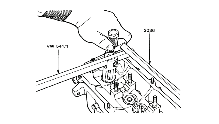
Figure 2-6-16 — Removal of Valve KeepersClick image to enlarge.

| 1. | Valve |
| 2. | Spring Seat |
| 3. | Stem Seal |
| 4. | Inner Valve Spring |
| 5. | Outer Valve Spring |
| 6. | Valve Spring Retainer |
| 7. | Valve Keepers |
Figure 2-6-17 — Valve Assembly ComponentsClick image to enlarge.
- Install tool 2036 on the mounting studs of camshaft bearing caps one and five and install four nuts and flat washers, see Figure 2-6-16.
- Using compressor tool VW 541/1, compress the valve springs of each valve assembly, remove both halves of each valve keeper (7) from each valve stem and set aside in order, see Figure 2-6-17.
- Remove the valve spring retainer (6), the inner spring (4), outer spring (5), stem seal (3) and spring seat (2) from each valve stem (1) and set aside in order.
CAUTION — Damage will occur to the valve guides during removal if burrs and roughness are not removed first.
- Feel all valve keeper grooves for roughness and, using either a small file, stone, or emery cloth, remove all burrs and roughness before withdrawing the valve from the cylinder head.
- Remove the valves from the cylinder head and set aside, in order.
20.Cleaning and Inspection — To clean and inspect, proceed as follows:

Figure 2-6-18 — Cylinder Head Distortion InspectionClick image to enlarge.

Figure 2-6-19 — Measurement of Cylinder Head ThicknessClick image to enlarge.

Figure 2-6-20 — Measurement of Valve Rocking PlayClick image to enlarge.

Figure 2-6-21 — Valve Spring Compression TestClick image to enlarge.
- Clean the valves with a wire brush.
- Using a straight edge and feeler gauge, check the sealing surface of the cylinder head for distortion, see Figure 2-6-18. If the distortion is greater than 0.1 mm, the head must be resurfaced. After resurfacing, the thickness of the head must not be less than 132.55 mm, see Figure 2-6-19.
- c. Using a dial indicator, measure the rocking play at each valve head. Move each valve stem back and forth in its guide and measure the stem movement, see Figure 2-6-20. The stem tip must be flush with the top of the guide. The maximum allowable rocking play of the intake valve stems is 1.0 mm. The maximum allowable rocking play of the exhaust valve stems is 1.3 mm. If the valve exceeds the allowable free play, install a new valve and measure the free play. If the new valve exceeds the allowable free play, replace the guide.
- Grind the intake valves, if necessary, to a 45° angle. The intake valves must have a minimum margin of 0.5 mm.
CAUTION — Do not grind exhaust valves. Exhaust valves can be lapped only.
- Inspect the cylinder head for cracks. Replace the cylinder head if any cracks are noted.
- Inspect the valve seats for burns and pitting and grind to 45 degrees, if necessary. Intake valves should have a maximum width of 2.00 mm and exhaust valves a maximum width of 2.40 mm. Lessen with a 30° stone.
- Using a valve spring tester, test the strength of the springs, see Figure 2-6-21. When the outer springs are compressed to 22.3 mm (7/8 in), the spring pressure should be 43.5 to 48 kg (96 to 106 lb). When the inner springs are compressed to 18.3 mm (23/32 in), the spring pressure should be 21.0 to 23.0 kg (46 to 51 lb). Replace valve springs as required.
- Place both halves of each valve keeper in the corresponding keeper groove on each valve stem. Rotate the valve while holding the keepers. The valve stem should rotate freely without excessive free play.
- Set aside all valve keepers in order.
- Lap each valve in its corresponding seat, see Figure 2-6-22.
- Clean all valves, stems and seats.

Figure 2-6-22 — Valve LappingClick image to enlarge.
- Apply a little Prussian blue to each valve at four points where the valve will contact the seat. Insert the valve stems into their corresponding guides and turn each valve a quarter turn in both directions. Withdraw the valves from the cylinder head and examine the circle of bluing on each valve. If the valves are correctly lapped, there will be a complete circle of bluing on each valve. If a circle is incomplete, lap the valve until a complete circle can be formed.
- Clean the bluing from the valves and seats and insert the valve stems into their corresponding guides.
- Place a covering over the bottom of the cylinder head so that the valves will not fall out when the cylinder head is turned over.
21.Installation — To install, proceed as follows:
- Place the spring seats over the corresponding valve stems.
- Place a plastic sleeve from the seal replacement kit on a valve stem to prevent damage when installing the valve stem seals.

Figure 2-6-23 — Installation of Valve Stem SealClick image to enlarge.
- Insert the spring end of a seal into valve seal installer tool 10-204, see Figure 2-6-23, and apply a coat of oil to the valve stem.
- Push the seal onto the valve stem and remove the plastic sleeve from the valve stem.
- Install seals on all valve stems following steps b., c. and d. and install the inner and outer springs and retainers on the corresponding valve stems.
- Place bar tool 2036 on the mounting studs of camshaft bearing caps one and five and install four nuts and flat washers.
- Using compressor tool VW 541/1, compress each set of valve springs and place both halves of each valve keeper in the corresponding keeper groove on each valve stem, see Figure 2-6-17.
- Remove bar tool 2036.
- Tap the top of each valve assembly to ensure the keepers are securely in place.
- Oil the bucket-type cam followers and shims and place on the corresponding valve assemblies.
- Install the camshaft and install bearing caps two and four. The bearing caps are offset. Ensure the caps are correctly positioned, see Figure 2-6-9.
- Install nuts and flat washers on both bearing caps. Tighten each nut a little at a time and torque to 20 N•m (15 ft lb).
- Install the front camshaft seal and install bearing caps one, three and five, ensuring the bearing caps are correctly positioned.
- Install two nuts and flat washers on each of the three bearing caps and torque to 20 N•m (15 ft lb).
- Install the cylinder head.
- To adjust the valves, refer to Section 8.
- Slide the timing belt tensioner onto the mounting stud and loosely install the locking nut and flat washer.
Valve Guides

Figure 2-6-24 — Pressing Out Valve Stem GuideClick image to enlarge.
22.Removal — To remove, proceed as follows:
- Remove the valves from the cylinder head.
- From the combustion side of the cylinder head, press out the guides using tool 10-206, see Figure 2-6-24.
23.Installation — To install, proceed as follows:
CAUTION — To prevent damage to the valve guide seating collars, do not use more than one ton of pressure after the seating collar contacts the cylinder head as the collar may break off.
- Lubricate new guides with oil and press into the cold cylinder head from the camshaft side ensuring the shoulder of each guide firmly contacts the top of the cylinder head.

Figure 2-6-25 — Reaming Valve GuideClick image to enlarge.
- Ream the valve guides using valve guide reamer 10-215 to obtain a uniform inside diameter of 8.013 to 8.035 mm, see Figure 2-6-25. Lubricate the reamer with cutting oil while reaming the guides.
- Check the diameter of the guide bores with a go/no-go gauge that has a go diameter of 8.013 mm and a no-go diameter of 8.035 mm. The 8.013 mm end of the gauge should enter the guides easily, but it should be impossible to insert the 8.035 mm end into the valve guides.
- Reface the valve seats.
- Install the valves.
Valve Stem Seals
(Cylinder Head Installed)
24.General — Replace all eight valve stem seals if there is any indication of seal leakage. Use the following removal and installation procedures when the cylinder head is installed on the engine block.
25.Removal — To remove, proceed as follows
- Place the piston at top dead centre (TDC).
- Place the vehicle in fourth gear and apply the hand brake.
- Remove the timing belt upper cover.
- Remove the valve cover.
- Remove the camshaft.
- Lift out the bucket-type cam followers and shims and set aside, in order, so that each bucket and shim will be reinstalled on the same valve assembly.
- Remove the spark plugs.
- h. Screw tool 653/3 into the cylinder at the opening for the spark plug and apply a minimum of 600 kPa (87 psi) to the cylinder.
- Install tool 2036 on the mounting studs of camshaft bearing caps one and five and install four nuts and flat washers, see Figure 2-6-17.
- Using compressor tool VW 541/1, compress the valve springs of each valve assembly, remove both halves of each valve keeper from each valve stem and set aside in order.
- Remove the valve spring retainer (6), the inner spring (4), outer spring (5), stem seal (3) and spring seat (2) from each valve stem (1) and set aside in order, see Figure 2-6-16. Use valve seal remover KD2899 to remove the seal.
26.Installation — To install, proceed as follows:
- Place the spring seats over the corresponding valve stems.
- Place a plastic sleeve from the seal replacement kit on a valve stem to prevent damage when installing the valve stem seals:
- Insert the spring end of a seal into valve seal installer tool 10-204, see Figure 2-6-23, and apply a coat of oil to the valve stem.
- Push the seal onto the valve stem and remove the plastic sleeve from the valve stem.
- Install seals on all valve stems following steps b., c. and d. and install the inner and outer springs and retainers on the corresponding valve stems.
- Using compressor tool VW541/1, compress each set of valve springs and place both halves of each valve keeper in the corresponding keeper groove on each valve stem.
- Remove bar tool 2036.
- Tap the top. of each valve assembly to ensure the keepers are securely in place.
- Remove tool 653/3.
- Apply a coat of oil to the bucket-type cam followers and place each bucket and shim on the corresponding valve assembly.
- Install the camshaft. Measure the tappet clearance for all valves and adjust as required (refer to Section 8).
- Install the valve cover.
- Install the timing belt upper cover.
- Install the spark plugs and cables (refer to Section 5).
Timing Belt Tensioner
27.Removal — To remove, proceed as follows:
- Remove the timing belt upper and lower covers.
- Remove the locking nut and spring washer from the tensioner mounting stud.
- Remove the timing belt.
- Slide the tensioner from the mounting stud.
28.Inspection — To inspect, ensure the tensioner turns freely and has no excessive free play in the bearing. Replace the tensioner, if necessary.
29.Installation — To install, proceed as follows:
- Install the tensioner on the mounting stud, ensuring the side of the tensioner with the adjusting nut is away from the cylinder head. Loosely install the spring washer and locking nut on the mounting stud.
- Install the timing belt and time the engine (refer to Section 8).
Camhaft Seal
(Camshaft Installed) 30.Removal — To remove, proceed as follows:
- Place the #1 piston at TDC on the compression stroke (refer to Section 5).
- Remove the timing belt upper cover.
- Loosen the locking nut for the timing belt tensioner and turn the tensioner until the tension of the belt is released.
- Remove the timing belt from the camshaft sprocket, ensuring the sprocket does not turn during the removal of the belt.
- Remove the bolt and flat washer from the camshaft sprocket and remove the sprocket and woodruff key.
- Using a suitable tool, remove the seal from the #1 bearing cap.
31.Installation — To install, proceed as follows:
- Inspect the seal mating surface of the camshaft for damage and replace the camshaft, if necessary.
- Lubricate the lips and outer surface of the new seal with oil.
- Place the seal on the end of the camshaft, ensuring the lips of the seal face inward and press the seal into the #1 bearing cap with tool 10-203 until the seal is fully home.
- Install the woodruff key and sprocket on the end of the camshaft, ensuring the side of the sprocket with the timing mark is nearest the valve cover.
- Install the retaining nut and flat washer for the sprocket and torque to 80 N•m (59 ft lb).
- Place the timing belt on the sprocket, ensuring the sprocket does not turn during the installation of the belt.
- Turn the tensioner clockwise until the timing belt has the correct tension and torque the locking nut to 45 N•m (33 ft lb).
- Check the timing marks and reset the timing, if required (refer to Section 8).
NOTE — Turn the crankshaft in the direction of rotation before checking timing belt tension. The belt has the correct tension when it can be twisted only though 90 degrees with the thumb and forefinger, or belt deflection is 15 mm.
- Install the timing belt upper cover and torque the retaining nuts to 10 N•m (7 ft lb).
Intermediate Shaft Seal
32.Removal — To remove, proceed as follows:
- Place #1 piston at TDC on the compression stroke (refer to Section 5).
- Remove the timing belt upper cover.
- Remove the drive belts (refer to Section 3).
- Remove the timing belt lower cover.
- Remove the timing belt.
- Remove the cap screw and flat washer from the intermediate shaft sprocket, slide the sprocket from the shaft and remove the woodruff key.

Figure 2-6-26 — Removal of Intermediate Shaft SealClick image to enlarge.
- Using a suitable tool, remove the shaft seal from the flange, see Figure 2-6-26.
NOTE — The intermediate shaft seal can also be removed and a new seal installed when the flange of the shaft has been removed from the engine block.
- If oil is leaking between the flange and the engine block, replace the flange “O” ring:
- Remove the two cap screws and lock washers from the flange.
- Remove the “O” ring from the flange.
- Place a new “O” ring on the flange.
- Place the flange over the end of the shaft. Install two cap screws and lock washers and torque to25 N•m (18 ft lb).
33.Inspection — Inspect the mating surface of the intermediate shaft for damage and wear and replace, if necessary.
34.Installation — To install, proceed as follows:
- Grease the new seal and start the seal into the flange, ensuring the lips of the seal face toward the engine block.

Figure 2-6-27 — Installation of Intermediate Shaft SealClick image to enlarge.
- Using tool 10-203, press the seal flush with the surface of the flange, see Figure 2-6-27.
- Install the woodruff key and intermediate shaft sprocket on the shaft, ensuring the side of the sprocket with the manufacturer's number is farthest from the engine block.
- Install the cap screw and flat washer for the sprocket and torque to 80 N•m (59 ft lb).
- Install the timing belt on the camshaft, crankshaft and intermediate shaft sprockets, ensuring the sprockets do not turn during the installation of the belt.
- Install the crankshaft pulley and check the timing marks. Reset the timing marks, if required.
- Remove the crankshaft pulley.
NOTE — Turn the crankshaft in the direction of rotation before checking timing belt tension. The belt has the correct tension when it can be twisted only through 90 degrees with the thumb and forefinger, or belt deflection is 15 mm.
- Turn the tensioner clockwise until the timing belt has the correct tension and torque the tensioner locking nut to 45 N•m (33 ft lb).
- Install the lower timing cover and torque the retaining screws and nuts to 10 N•m (7 ft lb).
- Install the pulley on the crankshaft and install the socket head screws. Do not torque at this time.
- Install the pulley on the coolant pump and install the socket head screws. Do not torque at this time.
- Install the drive belts and adjust the belt deflection to 15 mm. Tighten the alternator adjusting bolt and mounting bolt.
- Torque the crankshaft pulley and the coolant pump pulley screws to 20 N•m (15 ft lb).
- Install the timing belt upper cover and torque the retaining nuts to 10 N•m (7 ft lb).
Crankshaft Front Oil Seal
35.Removal — To remove, proceed as follows:
- Remove the drive belts.
- Remove the coolant pump and crankshaft pulleys.
- Remove the timing belt upper and lower covers.
- Remove the timing belt.
- Place the transmission in gear and apply the hand brake.
- Remove the crankshaft sprocket bolt and flat washer and pull the sprocket from the crankshaft. If necessary, use a universal puller or pry bar.

Figure 2-6-28 — Removal of Crankshaft Front Oil SealClick image to enlarge.
- Using a suitable tool, remove the front oil seal from the sealing flange, see Figure 2-6-28.
36.Inspection — Check the oil seal mating surface of the crankshaft for damage.
37.Installation — To install, proceed as follows:
- Apply oil to the lip and outer edge of the new seal and place the seal on the end of the crankshaft, ensuring the lips of the seal face toward the sealing flange.

Figure 2-6-29 — Installation of Crankshaft Front Oil SealClick image to enlarge.
- Using seal installer 10-203 and the flat washer from the crankshaft sprocket bolt, press the seal into the flange until the outer end of the seal is 2 mm inside the flange, see Figure 2-6-29.
- Install the sprocket on the end of the crankshaft.
- Apply Loctite #242 to the sprocket bolt. Install the bolt and flat washer and torque to 80 N•m (59 ft lb).
- Install the pulley with four socket head screws.
- Remove the timing plug from the flywheel housing and turn the crankshaft pulley until the timing mark on the flywheel is even with the timing indicator on the housing.

Figure 2-6-30 — Timing Mark of Intermediate Shaft Sprocket and Crankshaft PulleyClick image to enlarge.
- Turn the intermediate sprocket until the punch mark on the sprocket is in line with the timing mark on the crankshaft pulley, see Figure 2-6-30.
- Align the camshaft sprocket timing mark with the top of the rear timing belt plate, see Figure 2-6-7.
- Install the timing belt. Ensure that the sprockets do not turn during the installation of the belt.
- Check the timing marks and reset, if required.
- Turn the belt tensioner until the belt has the correct tension and torque the locking nut to 45 N•m (33 ft lb).
NOTE — Turn the crankshaft in the direction of rotation before checking timing belt tension. The belt has the correct tension when it can be twisted only through 90 degrees with the thumb and forefinger, or belt deflection is 15 mm.
- Remove the crankshaft pulley and install the timing belt lower cover.
- Install the crankshaft pulley.
- Install the coolant pump pulley.
- Install the drive belts.
- Torque the crankshaft and coolant pump pulley socket head screws to 20 N•m (15 ft lb).
- Install the timing belt upper cover and torque the retaining nuts and plug nut to 10 N•m (7 ft lb).
Alternator Brackets
38.Removal — To remove, proceed as follows:
- Remove the engine protection plate.
- Remove the alternator (refer to Section 5).
- Remove the timing belt upper cover.
- Remove the nut and flat washer that secure the timing belt lower cover to the coolant pump.
- Remove the coolant pump and crankshaft pulleys.
- Remove the socket head screw, located above the crankshaft timing sprocket, from the timing belt lower cover.
- Remove the cap screw and washer, located to the right of the crankshaft timing gear, from the timing belt lower cover.
- Pull the lower cover forward and remove the nut from the stud located near the top of the alternator front bracket.
- Remove the cap screw and washer near the bottom of the front bracket.
- Remove the cap screw and washer from the top of the rear timing plate.
- Pull the rear timing plate clear and remove the front bracket.
- Remove the two cap screws and washers from the rear alternator bracket and remove the bracket.
39.Installation — To install, proceed as follows:
- Install the alternator rear bracket with two cap screws and lock washers and torque to 20 N•m (15 ft lb).
- Install the front bracket with the cap screw and washer that secure the cover and bracket to the block. Torque the cap screw to 20 N•m (15 ft lb).
- Install the nut on the stud for the alternator bracket and timing belt rear plate and torque to 20 N•m (15 ft lb).
- Install the cap screw and washer at the top of the plate and torque to 10 N•m (7 ft lb).
- Install, to the right of the crankshaft timing gear, the cap screw and washer for the timing belt lower cover.
- Install, above the crankshaft sprocket, the socket head cap screw for the lower cover and torque to 10 N•m (7 ft lb).
- Install the coolant pump and crankshaft pulleys.
- Install the nut and washer for the lower cover at the coolant pump and torque to 10 N•m (7 ft lb).
- Install the timing belt upper cover.
- Install the alternator (refer to Section 5) and drive belts.
- Torque the coolant pump and crankshaft pulley cap screws to 20 N•m (15 ft lb).
- Install the engine protection plate.
Alternator Bracket Bushings
40.Removal — To remove, proceed as follows:
- Remove the alternator brackets.
- Press the bushings from the brackets.
41.Installation — To install, proceed as follows:
- Press new bushings into the brackets.
- Install the alternator brackets.
42.Removal — To remove, proceed as follows:
- Attach tool 2024A to the front lifting eye of the engine.
- Remove the self-locking nut and flat washer from each engine mounting bolt.
- Lift the engine so that the lifting sling supports the weight of the engine.
- Remove the three cap screws and washers from the left engine mounting bracket and remove the bracket.
- Remove the four cap screws and washers from the right engine mounting bracket and remove the bracket.
43.Installation — To install, proceed as follows:
- Install the right engine mounting bracket, with four cap screws and washers and torque to 25 N•m (18 ft lb).
- Install the left engine mounting bracket, with three cap screws and washers and torque to 55 N•m (41 ft lb).
- Lower the engine.
- Install a new self-locking nut and flat washer on each engine mounting bolt and torque to 45 N•m (33 ft lb).
- Remove tool 2024A.
Flywheel
44.Removal — To remove, proceed as follows:
- Remove the engine.
- Remove the clutch (refer to Part 3, Section 1).

Figure 2-6-31 — Tool 10-201 Installed on FlywheelClick image to enlarge.
- Install tool 10-201 to prevent the flywheel from turning, see Figure 2-6-31, and remove the six cap screws.
NOTE — It is not necessary to scribe the flywheel prior to removal. The flywheel will fit onto the crankshaft in one position only.
- Remove the flywheel from the crankshaft.
45.Inspection — To inspect, proceed as follows:
- Inspect the flywheel clutch surface for cracks and burns and replace, if necessary.
- Inspect the ring gear for broken and chipped teeth and replace the ring gear, if necessary.
- Inspect the crankshaft rear seal for leaks and the pilot bearing for wear and replace, if necessary.
46.Installation — To install, proceed as follows:
- Place the flywheel on the end of the crankshaft. Install the six flywheel cap screws and apply Loctite 271 to each cap screw.
- Install tool 10-201 and torque the flywheel cap screws to 75 N•m (55 ft lb).
- Install the clutch (refer to Part 3, Section 1).
- Install the engine.
Flywheel Ring Gear
47.Removal — To remove, proceed as follows:

Figure 2-6-32 — Location of Centre-Punched Points on Ring GearClick image to enlarge.
- Remove the flywheel.
- Centre punch two points on the ring gear, located 2.5 mm and 7.5 mm from the inside diameter of the gear and in line with the low part of a tooth, see Figure 2-6-32.
- Using a 3.5 mm drill, drill both holes to a depth of 6.5 mm.
- Cut through the remaining metal with a hacksaw and cold chisel until the ring gear breaks away from the flywheel.
48.Installation — To install, proceed as follows:
- Ensure the flywheel surface and the inner circumference of the ring gear are free of dirt and rough spots.
- Place the flywheel on a wood surface with the clutch surface facing down.

Figure 2-6-33 — Ring GearClick image to enlarge.
- Place the ring gear on the flywheel with the bevel on the inside diameter facing towards the flywheel, see Figure 2-6-33.
- Place a piece of 50/50 solder on the upper face of the gear.
- Press the solder down and ensure it makes good contact with the gear.
- Hold the gear away from the flywheel with tongs and heat the gear with a welding torch, running the flame around the gear to obtain even heating. Do not direct the flame at the solder.
- When the solder begins to melt, approximately 200°C., brush off the solder and install the gear on the flywheel.
- Drive the gear evenly into position at diagonally opposite positions on the upper face, using a brass drift and hammer.
- Allow the gear to cool and check for tightness.
- Install the flywheel.
Crankshaft Pilot Bearing
49.Removal — To remove, proceed as follows:
- Remove the engine.
- Remove the clutch and pressure plate (refer to Part 3, Section 1).
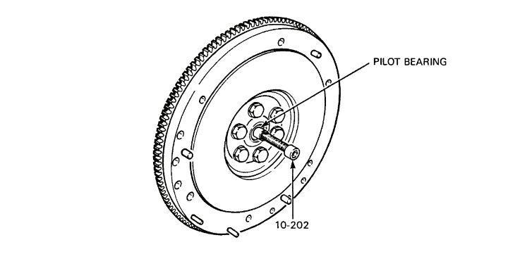
Figure 2-6-34 — Removal of Crankshaft Pilot BearingClick image to enlarge.
- Using extractor 10-202, remove the pilot bearing from the crankshaft, see Figure 2-6-34.
50.Installation — To install, proceed as follows:
NOTE — To ensure that the pilot bearing seal is correctly positioned, install the bearing with its lettering facing outwards.

Figure 2-6-35 — Installation of Crankshaft Pilot BearingClick image to enlarge.
- Place a new pilot bearing on the end of the bearing installer tool VW207C and install the bearing, see Figure 2-6-35. If the engine is mounted on a stand, tap in the bearing using a plastic hammer.
- Drive the bearing into the crankshaft and remove the bearing installer tool. The bearing should be 1.5 mm inside the end of the crankshaft.
- Install the clutch and pressure plate (refer to Part 3, Section 1).
- Install the engine.
Crankshaft Rear Oil Seal

Figure 2-6-36 — Removal of Crankshaft Rear Oil SealClick image to enlarge.
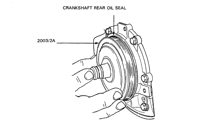
Figure 2-6-37 — Installation of Crankshaft Rear Oil Seal with Tool 2003/2AClick image to enlarge.

Figure 2-6-38 — Installation of Crankshaft Rear Oil Seal with Tool 2003/1Click image to enlarge.
51.Removal — To remove, proceed as follows:
- Remove the engine.
- Remove the clutch (refer to Part 3, Section 1).
- Remove the flywheel.
- Using pry lever 10-221, remove the oil seal from the crankshaft, see Figure 2-6-36.
52.Installation — To install, proceed as follows:
- Coat the lips of the new seal with grease or oil.
- Using seal installer tool 2003/2A, start the seal into the crankshaft, ensuring the lips of the seal face toward the crankshaft, see Figure 2-6-37. Tap the tool lightly to ensure the seal will enter the crankshaft in a straight line.
- Using installation tool 2003/1 and two flywheel cap screws, press the seal fully home, see Figure 2-6-38, and remove the tool and cap screws.
- Install the flywheel.
- Install the clutch (refer to Part 3, Section 1).
- Install the engine.
Section 7 — Power Pack
General
Power Pack Description
1.The power pack consists of the engine, clutch and transaxle.
2.The power pack is attached to the vehicle frame by four brackets; one on each side of the engine block and one on each side of the transaxle.
Component Removal and Installation
WARNING — Do not replace metric bolts with standard bolts. See the WARNING at the front of the manual.
Power Pack
3.Removal — To remove, proceed as follows:
- Disconnect the battery ground cable.
- Drain the cooling system (refer to Section 8).
- Remove/disconnect the following cooling system components:
- Remove the expansion reservoir (refer to Section 3).
- Remove the radiator and fan assembly (refer to Section 3).
- Disconnect the coolant hose “T” junction from the heater hose leading to the firewall.
- Disconnect the heater return hose from the rear of the cylinder head and cap the opening.
- Remove the four radiator grille bolts and lift the grille from the engine compartment.
- Remove the four slotted cap screws, flat and lock washers from the radiator mounting bracket and remove the bracket.
- Remove the two cap screws, flat and lock washers from the radiator guard at the front crossmember and remove the guard.
- Remove the two front crossmember cap screws, flat and lock washers and remove the front crossmember.
- Remove the front bumper (refer to Part 6, Section 2).
- Complete the following carburetor disconnections:
- Remove the air intake hose from the carburetor to the air filter housing.
- Remove the distributor ventilation hose from the air filter housing.
- Remove the breather hose from the valve cover.
- Loosen the screw from the choke cable, casing and hose at the bracket and the screw from the choke cable at the choke lever and pull the cable, casing and hose away from the carburetor.
- Disconnect the fuel line from the carburetor.
- Remove the two fuel by-pass reservoir mounting bolts and move the reservoir and in-line fuel filter out of the way.
- Pull out the two spring clips on both sides of the rubber grommet on the accelerator cable that secure the cable to the bracket.
- Remove the clip from the accelerator cable at the throttle shaft sector plate and disconnect the cable tip.

Figure 2-7-1 — Carburetor Air/Fuel Cutoff ValveClick image to enlarge.
- Disconnect the electrical lead from the air/fuel cutoff valve at the carburetor, see Figure 2-7-1.
- Disconnect the vacuum advance line from the carburetor.
- Disconnect the vacuum advance line and brake servo vacuum lines from the intake manifold, and disconnect the vacuum retard line and the distributor ventilation line from the brake servo vacuum line “T” fittings.
- Complete the following electrical disconnections:
- Disconnect the two wire leads from the starter solenoid.
- Disconnect the main terminal wire from the starter.
- Disconnect the engine ground strap from the left fender panel.
- Remove the alternator terminal protection cover from the alternator.
- Disconnect the electrical wires from the rear of the alternator.
- Disconnect the wire lead to the oil temperature sending unit at the oil filter housing.
- Disconnect the TCI electrical connector from the base of the distributor.
- Disconnect the wire to the oil pressure sending unit at the rear of the cylinder head.
- Disconnect the wires from the coolant temperature and temperature warning light sending units.
- Disconnect the coil HT cable from the coil.
- Disconnect the electrical connector from the two-wheel drive sending unit.
- Disconnect the block heater cord from the clip on the fender panel.
- Complete the following transaxle disconnections:
- Disconnect the breather hose from the clutch housing.

Figure 2-7-2 — Clutch Cable at Engine Mounting BracketClick image to enlarge.

Figure 2-7-3 — Two-Wheel Drive Linkage at Two-Wheel Drive LeverClick image to enlarge.
- Pull the cable from the engine mounting bracket and disconnect the clutch cable from the clutch lever, see Figure 2-7-2.
- Disconnect the vent hose from the clutch housing.
- Cap the breather and vent hose openings.
- Unscrew the speedometer cable from the speedometer drive housing and cap the unit.
- Remove the six socket head screws and three tab locks from the front constant velocity joint of the propeller shaft at the transaxle and lower the shaft.
- Disconnect the return spring on the two-wheel drive linkage at the shift lever, see Figure 2-7-3.
- Disconnect the two-wheel drive linkage at the shift lever by removing the spring lock and clevis pin.
- Remove the six nuts from the exhaust pipe at the manifold.

Figure 2-7-4 — Muffler HangerClick image to enlarge.
- Remove the front muffler hanger bolt and nut, see Figure 2-7-4. Pull the exhaust pipe away from the manifold and remove the gasket.
- Remove the gear shift lever and tower from the transmission (refer to Part 3, Section 1).
- Remove the six socket head screws and three tab locks from each inner constant velocity joint of the front drive axles and slide both drive axles away from the transaxle.
- Ensure the wheels are chocked and the hand brake applied. Remove the two engine mounting bolts and thick washers from the engine mounting brackets.
- Attach lifting sling 2024A to the front and rear lifting eyes of the engine. Lift the power pack slightly with a hoist and remove the washers and support pads.
- Remove the two transaxle mounting bolts, thick washers, and support pads from the transaxle mounting brackets.
- Lift the power pack from the engine compartment.
4.Installation — To install, proceed as follows:
NOTE — To ensure ease of installation, the gear shift lever tower must be removed from the transaxle, refer to Section 1. Cap the opening.
- Ensure the wheels are blocked and the hand brake applied.
- Place an upper support pad and washer on both engine mounts.
- Clean and inspect the area of the vehicle where the power pack will be installed.
- Attach a lifting sling 2024A to the front and rear lifting eyes of the engine and raise the Power pack.
CAUTION — To prevent vehicle damage when guiding the power pack into the vehicle, ensure the exhaust manifold does not bind against the exhaust pipe and the twowheel drive shift linkage is clear of the transaxle mounts.
- Guide the power pack into the engine compartment until the engine mounting brackets rest lightly on the engine mounts. If necessary, lower and tilt the engine slightly so that the transaxle will pass between the steering rack assembly and the vehicle frame crossmember below the rack assembly.
- Insert a lower support pad and washer into the bottom of both engine mounts.
- Insert an engine mounting bolt through the bottom of both engine mounts and install a thick washer and nut but do not tighten.
- Place an upper support pad and washer on both transaxle mounts.
- Align the transaxle mounting brackets with the transaxle mounts and insert a lower support pad and washer into the bottom of each mount.
- Install a mounting bolt through the bottom of both transaxle mounts and install a thick washer and nut but do not tighten.
- Lower the power pack so that the engine and transaxle mounts support the weight of the power pack.
- Raise the front end of the propeller shaft and install the three tab locks and six new socket head screws for the front constant velocity joint. Torque the socket head screws to 45 N•m (33 ft lb).
- Torque the engine mounting bolts to 45 N•m (33 ft lb) and the transaxle mounting bolts to 40 N•m (30 ft lb).
- Install the front drive axle assemblies to the transaxle:
- Position the inner constant velocity joints of the front drive axles against the differential flanges and install three locking plates and six new socket head screws.
- Torque the socket head screws to 45 N•m (33 ft lb).
- Complete the following transaxle connections:
- Remove the cap from the speedometer drive housing and install the speedometer cable.
- Remove the caps from the clutch housing breather and vent opening.
- Install the clutch housing breather hose.
- Install the clutch housing vent hose.
- Attach the end of the clutch cable to the hook on the clutch lever and push the cable into the cable opening in the engine mounting bracket.
- Connect the two-wheel drive shift linkage at the shift lever by installing the spring lock and clevis pin.
- Connect the return spring to the two-wheel drive shift linkage at the shift lever.
- Install the transmission shift tower (refer to Part 3, Section 1).
- Complete the following electrical connections:
- Connect wires #80 and #91F to the two-wheel drive sending unit terminal.
- Connect the coil HT cable to the coil.
- Connect wire #33 to the coolant temperature sending unit and wire #32 to the coolant temperature warning light sending unit.
- Connect electrical wires #35 and #36 to the oil pressure sending unit terminal.
- Connect electrical wire #34 to the oil temperature sending unit terminal.
- Connect the TCI electrical connector at the base of the distributor.
- Connect negative (–) wire #52 to the alternator negative (–) terminal.
- Connect wire #1 to the regulator D+ terminal, see Figure 2-5-11.
NOTE — The manufacturer recommends that if a new, or rebuilt, alternator is installed, momentarily flash the field. Connect one end of a jumper cable to the diode trio terminal on the regulator and touch the other end of the jumper cable to the positive (+) terminal of the alternator for a few seconds, see Figure 2-5-11.
- Connect wire #1D to the regulator terminal.
- Install the alternator terminal protection cover.
- Install the engine ground strap to the left fender panel.
- Connect the battery master switch wire #6 and alternator cables #2 to starter terminal #30.
- Connect ignition wire #37B to starter terminal #15A and starter button wire #74A to terminal #50.
- Attach the block heater cord to the clip on the fender panel.
- Complete the following vacuum line connections:
- Install the brake servo vacuum line on the intake manifold.
- Install the vacuum advance line from the front of the vacuum advance unit to the carburetor.
- Install the vacuum retard line to the brake servo vacuum line at the “T” fitting closest to the intake manifold.
- Install the distributor ventilation hose to the brake servo vacuum line at its “T” fitting.
- Raise the muffler and install the front hanger securing bolt.
- Install a new gasket on the exhaust pipe, fit the end of the pipe to the studs on the exhaust manifold and install six nuts.
- Complete the following carburetor connections:
- Install the accelerator cable and check adjustment.
- Connect the electrical lead to the air/fuel cutoff valve terminal.
- Install the choke cable and check adjustment.
- Install the carburetor air intake hose to the carburetor and to the air cleaner assembly.
- Install distributor ventilation hose to the filter housing.
- Install the fuel by-pass reservoir on the right fender panel and install two bolts.
- Install the fuel line on the carburetor.
- Install the breather hose on the valve cover.
- Install the front bumper (refer to Part 6, Section 2).
- Install the following cooling system components:
- Install the front crossmember with two cap screws, flat and lock washers.
- Install the radiator guard to the front of the front crossmember with two cap screws, flat and lock washers.
- Install the radiator mounting bracket with four slotted cap screws, flat and lock washers.
- Slide the radiator grille into place behind the headlight cover plates and secure the grille with four cap screws and flat washers.
- Install the radiator and fan assembly (refer to Section 3).
- Install the expansion reservoir (refer to Section 3).
- Install the heater return hose to the coolant hose “T” junction.
- Remove the cap from the rear of the cylinder head and install the remaining heater hose.
- Connect the battery ground cable.
- Fill the cooling system (refer to Section 8).
Section 8 — Maintenance and Adjustments
Fuel System
Carburetor Adjustments
Cold Idling Speed Adjustment
1.Adjustment — To adjust, proceed as follows:
- Ensure the engine temperature is a minimum of 60°C (140°F).
- Connect a tachometer to the engine.
- Start the engine and adjust the idle speed between 900 and 1,000 rpm.
- Stop the engine and remove the carburetor air intake hose from the carburetor.
- Pull the choke cable fully out and check the choke valve operating lever. The lever should be against the stop. Adjust the cable, if necessary.

Figure 2-8-1 — Cold Idling Speed CheckClick image to enlarge.
- Ensure the mark on the disc points to the centre of the adjusting screw, see Figure 2-8-1. If necessary, loosen the clamping screw and rotate the disc until the mark on the disc points to the centre of the adjusting screw and tighten the clamping screw.
- Without pressing the accelerator pedal, start the engine. With the choke fully open, the engine speed should be between 3,000 and 3,600 rpm.
- If necessary, adjust engine speed to 3,300 rpm. Turn the adjusting screw on the choke clockwise to increase rpm or counter-clockwise to decrease engine rpm.
- Install the carburetor air intake hose to the carburetor and disconnect the tachometer from the engine.
Carburetor Pulldown Unit Inspection
2.Inspection — To inspect, proceed as follows:
- Remove the carburetor air intake hose from the carburetor.
- Start and run the engine at idling speed.
- Pull the choke cable fully out and close the choke valve by hand. If the choke valve can be easily closed to a gap of about 4 mm before resistance is felt, the pulldown unit is operating correctly. If the choke valve can be completely closed without resistance, the pulldown diaphragm is split or there is a leak in the vacuum system.
- Install the carburetor air intake hose to the carburetor.
Choke Valve Gap Adjustment

Figure 2-8-2 — Measurement of Choke Valve GapClick image to enlarge.
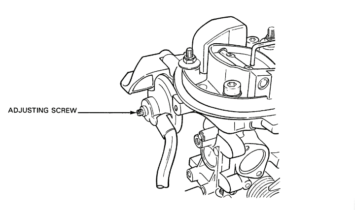
Figure 2-8-3 — Choke Valve Gap AdjustmentClick image to enlarge.

Figure 2-8-4 — Choke Cover and Choke Body AlignmentClick image to enlarge.
3.Adjustment — Ensure the carburetor pulldown unit is operating correctly before adjusting the choke valve gap. To adjust the gap, proceed as follows:
- Pull the choke cable fully out.
- Loosen the choke cover screws and rotate the cover counter-clockwise until the choke valve is closed and tighten the cover screws.
- Using a screwdriver, push the pulldown operating rod in the direction of the pulldown unit until the rod contacts the stop and, using a feeler gauge, measure the choke valve gap on the enrichment tube side of the valve, see Figure 2-8-2. The valve gap should be between 3.85 and 4.15 mm.
- If necessary, adjust the choke valve gap. Turn the adjusting screw on the pulldown unit clockwise to decrease the gap and counter-clockwise to increase the gap, see Figure 2-8-3.
- Realign the mark on the choke cover with the mark on the choke body, see Figure 2-8-4 and tighten the cover screws.
Air/Fuel Cutoff Valve Inspection
4.Inspection — To inspect, proceed as follows:
- Disconnect the electrical wire from the air/fuel cutoff valve terminal.
- Turn the accessory switch “ON”.
- Touch the wire to the air/fuel cutoff valve terminal several times. A clicking sound should be heard if the valve is operating correctly.
- Turn the accessory switch “OFF”.
- Connect the wire to the cutoff valve terminal.
Carbon Monoxide (CO) Content Adjustment
5.Adjustment — Adjust the CO content after adjusting the ignition timing. To adjust, proceed as follows:
- Ensure the exhaust system does not leak.
- Ensure the engine is at normal operating temperature.
- Ensure all electrical accessories are turned off.
- Remove the crankcase breather hose from the valve cover and plug the hose.
- Ensure the choke is fully open.
- Ensure the idle speed is set between 900 and 1,000 rpm.
- Ensure the ignition timing is properly set.
- Ensure the cooling fans are not operating.
- Connect the exhaust analyzer following the manufacturer's instructions.
- Start the engine and allow it to run for five minutes.
- Note the meter reading of the carbon monoxide content and adjust the carburetor CO needle valve until a reading of 0.5 to 1.5% volume of carbon monoxide is obtained.
- Install the plug over the CO screw.
- Unplug the crankcase breather hose and install the hose to the valve cover.
- Note that an increase in CO level after connecting the crankcase breather hose results from fuel enrichment in the crankcase due to oil dilution. If necessary, change the oil to reduce the CO level.
- Disconnect the exhaust analyzer.
Cooling System
Draining the Cooling System
6.To drain, proceed as follows:
- Remove the engine protection plate.
- Remove the radiator protection plate.
- Remove the expansion reservoir cap.
WARNING — To prevent injury, allow the engine to cool before draining the cooling system.
- Place a suitable drain pan under the radiator drain plug, remove the plug and drain the radiator, or place a drain pan under the thermostat housing, remove the hose at the bottom of the housing and allow the coolant in the radiator to drain.
- Remove the two cap screws from the thermostat housing.
- Pull the thermostat housing, gasket and thermostat from the coolant pump housing and allow the coolant in the engine and heater to drain.
- Cap the opening after the system is completely drained.
FILLING THE COOLING SYSTEM
7.To fill, proceed as follows:
- Install the thermostat in the coolant pump housing and install the gasket.
- Install the housing over the end of the thermostat. Install two cap screws through the housing and into the coolant pump housing. Torque the cap screws to 10 N•m (7 ft lb).
- Install the lower radiator hose to the bottom of the thermostat housing.
- Loosen the heater core bleeder valve.
- Fill the cooling system until the coolant level in the expansion reservoir reaches the arrow (minimum level) marked on the reservoir.
- Start the engine and allow it to run until the coolant fills the cooling system.
- Close the heater core bleeder valve when coolant starts to drip from the valve.
- Turn the engine off and add more coolant, if required.
- Install the expansion reservoir cap.
- Inspect the cooling system for leaks.
- Install the radiator protection plate.
- Install the engine protection plate.
Expansion Reservoir Cap Pressure Test

Figure 2-8-5 — Expansion Reservoir Cap Pressure TestClick image to enlarge.
8.Test — To test, proceed as follows:
- Remove the cap and inspect the gasket. Replace the gasket, if necessary.
- Screw the cap onto pressure tester adapter VW 1274/1A and attach the adapter to the pressure tester VW 1274, see Figure 2-8-5.
- Pump up the pressure and note the pressure when the relief valve opens. If the relief valve does not open between 120 and 135 kPa (17.4 to 19.6 psi), replace the cap.
Cooling System Pressure Test

Figure 2-8-6 — Adapter VW 1274/1A Installed on Expansion ReservoirClick image to enlarge.
9.Test — To test, proceed as follows:
- Screw the pressure tester adapter VW 1274/1A onto the expansion reservoir, see Figure 2-8-6.
- Attach the tester to the adapter and pump up the pressure to 100 kPa (14.5 psi). If the pressure drops off, check for leaks in the system.
ENGINE ELECTRICAL
ALTERNATOR TESTS
10.General — Before performing any alternator tests, check the following:
- Ensure the batteries are warm and in a good state of charge.
- Ensure the drive belts are properly adjusted.
- Ensure all positive and negative connections between the alternator and batteries are clean and tight.
11.Test — To test the alternator output voltage, proceed as follows:

Figure 2-8-7 — Alternator Testing OrderClick image to enlarge.
- Run the engine at a fast idle and measure the voltage across the batteries. The voltage should be between 27.9 and 28.1. If the voltage is not within the specified limits, adjust alternator output voltage.
- Run the engine with all the accessories on or connect a carbon pile across the batteries (do not exceed the alternator output rating). The battery voltage should be a minimum of 27 volts. If battery voltage is less than 27 volts, perform the alternator full-fielded output voltage test. Complete the alternator tests following the order presented in Figure 2-8-7. If the alternator passes the tests described in steps a. and b., no further testing of the alternator is required.
Alternator Output Voltage Adjustment
12.Adjustment — To adjust, proceed as follows:
- Start the engine and run between 1,000 and 1,200 rpm.
- Set the meter to the 60 DC volt scale.
- Connect the meter positive lead to the positive terminal of the right battery and the negative lead to the negative terminal of the left battery.
- Note the meter reading. If the meter reading is between 27.9 and 28.1 volts, the charging system is serviceable. If the meter reading is not within this range, the alternator output voltage requires adjustment.

Figure 2-8-8 — Nylon Plug in Alternator RegulatorClick image to enlarge.
- Remove the slotted nylon plug from the alternator regulator, see Figure 2-8-8.
CAUTION — Do not force the adjusting screw in either direction.
- Turn the adjusting screw clockwise to increase voltage output. If the voltage rises above 28.1 volts, turn the adjusting screw counter-clockwise to reduce the voltage. If the alternator output voltage cannot be increased, perform the full-fielded output voltage test.
- Turn “OFF” the accessory switch and install the nylon plug in the regulator.
- Disconnect the meter leads to the battery terminals.
Alternator Full-fielded Output Voltage Test
13.Test — If the alternator output voltage is very low or nil, perform the full-fielded output voltage test. To full-field the alternator, proceed as follows:
- Connect a jumper wire to the alternator negative terminal.

Figure 2-8-9 — Full-Fielding the AlternatorClick image to enlarge.
- Attach a short piece of wire to the other end of the jumper cable and insert the wire into the small hole in the end of the brush holder so that the wire contacts the outer brush terminal, see Figure 2-8-9.
- Connect a voltmeter across the batteries.
CAUTION — To prevent damage to the electrical system by unregulated voltage, do not run the engine above 1,200 rpm.
- Start and run the engine at 1,200 rpm.
- Note the meter reading. Replace the alternator if the voltage does not rise. If the meter indicates a rise in voltage, the alternator is serviceable and the fault may be in the diode trio or voltage regulator. Test the diode trio and voltage regulator.
- Turn the accessory switch “OFF”. Withdraw the wire from the alternator and disconnect the jumper cable from the alternator negative terminal.
Alternator Diode Trio Test
14.Test — If the full-fielded output voltage test indicates that the alternator is serviceable, test the diode trio. To test, proceed as follows:

Figure 2-8-10 — Diode Trio Output Lead and #1 WireClick image to enlarge.

Figure 2-8-11 — Diode TrioClick image to enlarge.
- Disconnect the battery ground cable.
- Disconnect the diode trio output lead and the #1 wire from the regulator, see Figure 2-8-10.
- Remove the three screws, flat and lock washers from the diode trio and remove the diode trio from the alternator.
- Set the meter to the RX1 ohms scale and zero the meter.
- Connect the meter negative probe to the output lead of the diode trio and touch the positive probe to each of the three diode trio terminal pads, see Figure 2-8-11. If there is needle deflection for any one of the terminal pads, replace the diode trio.
- Connect the meter positive lead to the output lead of the diode trio and touch the negative lead to each of the three terminal pads. The needle deflection of the meter should be similar for all three terminal pads. If there is not similar needle deflection for all three pads, replace the diode trio. If the alternator and diode trio are operating correctly, test the alternator voltage regulator.
- Install the diode trio on the alternator ensuring the lead is toward the rear of the alternator and install the three securing screws, flat and lock washers.
- Install the diode trio lead and wire #1 to the regulator.
- Connect the battery ground cable to the battery ground terminal.
- Start the engine and perform the output voltage test.
Alternator Voltage Regulator Test
15.Testing the voltage regulator can only be done by substitution. If the alternator full-fielded output voltage and the diode trio tests indicate that the alternator is serviceable, replace the voltage regulator and perform the output voltage adjustment.
Engine Mechanical
Valve Tappet Clearance Adjustment
16.Adjustment — To adjust, proceed as follows:
- Remove the valve cover (refer to Section 6).
- Turn the crankshaft so that the two camshaft lobes for one of the cylinders are facing up at similar angles.
- Using a feeler gauge measure the clearance between each camshaft lobe and corresponding shim for the intake and exhaust valves of the cylinder.
NOTE — When cold, the clearance between the intake valves and camshaft lobes should be between 0.15 mm and 0.25 mm. When cold, the clearance between the exhaust valves and camshaft lobes should be between 0.35 mm and 0.45 mm.
- If the clearance is not within the specified clearance range, remove the shim and install a new shim that is the correct thickness. Proceed as follows:

Figure 2-8-12 — Pressing Bucket Type Cam FollowersClick image to enlarge.
- Turn the bucket-type cam followers so that both slots in the bucket face toward the sides of the cylinder head.
- Using compressing tool Hazet 2078, press both buckets down, see Figure 2-8-12.
- Using shim pliers tool 10-208, remove the shim from the buckets. If shim pliers are not available, use low air pressure to remove the shim.
Engine Valve Timing Check
17.Check — The engine valve timing check is normally used to check engine valve timing, when removing a distributor or when replacing camshaft, intermediate shaft or crankshaft oil seals. This procedure will place #1 piston on TDC on compression stroke. To check, proceed as follows:
- Remove the plug from the flywheel housing and turn the crankshaft pulley until the timing mark on the flywheel is in line with the timing indicator on the flywheel housing, see Figure 2-5-16.
- Remove the oil filler cap from the valve cover and ensure that both camshaft lobes of the #1 cylinder face upwards at similar angles, see Figure 2-5-17. If the lobes do not face upwards, rotate the crankshaft one complete revolution.
NOTE — With the camshaft lobes facing upward at the same angle, the timing mark on the rear of the camshaft sprocket will be even with the top edge of the rear timing belt plate, see Figure 2-6-7.
- If the timing marks in the above subparas a. and b. do not coincide, the engine valve timing will require adjusting.
- Remove the timing belt upper and lower covers and the timing belt.
- Turn the camshaft sprocket until the timing mark on the sprocket is even with the tip at the top of the timing belt rear plate. Both camshaft lobes of the #1 cylinder must face up at similar angles.
- Install the crankshaft pulley on the crankshaft, ensuring the indentation on the pulley engages in the protrusion on the crankshaft sprocket and install the cap screws and flat washers.
- Remove the timing plug from the flywheel housing and turn the crankshaft pulley until the timing mark on the flywheel is even with the timing mark indicator on the flywheel housing.
- Turn the intermediate sprocket until the punch mark on the sprocket is in line with the “V” mark on the crankshaft pulley.
- Remove the crankshaft pulley, ensuring the crankshaft sprocket does not turn, and place the timing belt on the crankshaft, intermediate shaft and camshaft sprockets. Ensure the sprockets do not turn when the belt is installed. Ensure the teeth of the belt are correctly engaged in the sprockets, and all the slack of the timing belt is on the side nearest the tensioner.
- Turn the timing belt tensioner clockwise and adjust the belt to a 15 mm deflection (or when the belt can only be twisted to a 90 degree angle with thumb and forefinger) measured at the midpoint between the camshaft and intermediate sprockets, see Figure 2-6-13. Tighten and torque the locking nut to 45 N•m (33 ft lb).
CAUTION — Do not turn the tensioner counterclockwise when adjusting the belt, as the tensioner will rub and wear a hole through the belt lower cover.
- Rotate the crankshaft through two complete revolutions in the direction of normal engine rotation, and recheck the engine timing and belt tension.
- Install the plug in the flywheel housing.
- Install the timing belt covers and valve cover. Torque the nuts and screws to 10 N•m (7 ft lb).
- Install the crankshaft pulley on the crankshaft, ensuring the indentation on the pulley engages in the protrusion on the crankshaft sprocket and install the cap screws and flat washers.
- Place the coolant pump pulley on the coolant pump, ensuring the pulley is aligned with the crankshaft pulley and install the cap screws and flat washers.
- Install the drive belts. Adjust to 15 mm of deflection and tighten the alternator adjusting bolt and mounting bolt.
- Torque the crankshaft and coolant pump pulleys to 20 N•m (15 ft lb).
Cylinder Compression Test
18.Test — A compression test will indicate the condition of the valve seating, compression ring sealing and the sealing surfaces of the engine block and cylinder head. To test, proceed as follows:
- Start and warm up the engine to about 40°C (104°F).
- Remove the spark plugs (refer to Section 5).
- Disconnect the coil HT cable from the distributor cap and connect the cable to a good ground.
- Install the compression gauge in a spark plug opening.
- Hold the throttle valve fully open and crank the engine until the needle of the compression gauge stops rising and record the reading.
- Repeat steps d. and e. for the remaining three cylinders. The cylinder compression for a new engine should be 900 to 1,200 kPa (130 to 174 psi). The minimum allowable cylinder compression is 700 kPa (101 psi). The maximum allowable difference between cylinders is 300 kPa (43 psi).
- Connect the coil high tension cable to the distributor cap.
- Install the spark plugs (refer to Section 5).
Ignition System
Primary Ignition System Tests
19.Perform the primary ignition system tests in the following order:
- Ballast resistor to coil cable test.
- Coil primary and secondary resistance test.
- Coil voltage test.
- Distributor pick-up coil test.
- Distributor pick-up coil dynamic test.
- Primary circuit switching test.
- Ballast resistor test.
NOTE — Distributor cap and rotor tests are described in Section 5.
20.Prior to performing the ignition system tests, ensure that the batteries are in a good state of charge and all electrical connections are clean and tight.
NOTE — Always ensure the multimeter is connected to a clean engine ground.
Safety Precautions
21.General
- Do not touch the high tension cables when the engine is running or being cranked by the starter.
- Only disconnect high tension cables when the accessory switch is “OFF”.
- Only attach and detach test equipment when accessory switch is “OFF”.
- Do not connect a suppression condensor or test lamp to coil terminal #1 (—).
- Do not connect test equipment or a timing light with 24 Vdc supply to coil terminal #15.
- After disconnecting the coil high tension cable from the distributor, always connect the cable directly to ground. If not connected to ground, the engine must not be cranked at starter speed (e.g., when doing compression test or TCI control unit test).
- Do not use a quick charger as a starting aid.
- Do not replace the coil with a standard coil.
- When welding with electric arc or spot welding, the batteries must be disconnected (negative and positive).
- Do not spray water on the engine when the accessory switch is “ON”.
22.Test — To test, proceed as follows:
CAUTION — Use care when removing or installing cables to prevent them from twisting and breaking.
- Disconnect the cable from coil terminal #15 (+).
- Set the multimeter to the 60 Vdc scale.
- Attach the positive meter lead to the cable and the negative lead to a good engine ground.
- Turn the accessory switch “ON” and note the meter reading. The reading should be battery voltage. If no reading, or a low reading is obtained, check the suppressor, ballast resistors, wiring, accessory switch and battery connections. Repair or replace components as required.
Coil Primary and Secondary Resistance Test
23.Test — To test, proceed as follows:
- Disconnect the cable from coil terminal #1 (—).
- Set the multimeter to the RX1 ohms scale.
- Install adapters Z401139WE in terminals #1 and #15.
- Connect the meter leads to coil terminals #1 and #15 and check the meter reading. The reading should be 0.81 to 0.99 ohms. If the reading is not within the specified limits, replace the coil.
- Set the meter to the RX1K ohm scale.
- Connect the meter leads to coil terminals #1 and #4 and check the meter reading. The meter reading should be 6,210 to 7,590 ohms. If the meter reading is not within the specified limits, replace the coil.
Coil Voltage Test
24.Test — To test, proceed as follows:
- Install adapters Z401139WE on coil terminals #1 and #15 and connect the cables to the terminals.
- Connect the HT cable to coil terminal #4.
- Set the multimeter to the 60 Vdc scale.
- Connect the positive meter lead to the adapter on the #1 terminal and the negative lead to a good ground.
- Turn the accessory switch “ON” and note the meter reading. The reading should be about two volts for a few seconds and then stabilize at battery voltage.
- Turn the accessory switch “OFF” and connect the meter positive lead to the adapter on coil terminal #15.
- Turn the accessory switch “ON” and note the meter reading. The meter reading should be about seven volts for a few seconds and then stabilize at battery voltage. If the readings are not within the specifications, disconnect the cables and ensure the end connectors are clean and the cables in good condition.
- Connect the cables to the coil terminals and do the coil voltage test again.
- Replace the TCI unit if the readings are not within the specified limits.
Distributor Pick-up Coil Test
25.Test — To test, proceed as follows:
NOTE
- If engine won't run when hot or runs intermittently, test pick-up coil when hot.
- Transmission of signal generated in the pick-up coil requires that distributor to TCI unit connections be absolutely clean, mechanically tight and free of corrosion.
- Disconnect the distributor lead from the TCI unit and ensure the connection is clean.
- Set the multimeter to the RX1K ohm scale.
- Connect the meter leads to terminals A and B of the cable and note the meter reading. If necessary, insert pieces of clean wire into the terminals and connect the meter leads to the terminals. The meter reading should be 0.99 to 1.21K ohms.
- Connect meter leads to terminals B and C, and A and C. Note the meter reading. There should be no reading.
- If the meter readings are not within the specifications, remove the cable and check continuity: A to A, B to B, and C to the cable casing. If the continuity check is satisfactory, replace the pickup coil on the distributor.
Distributor Pick-up Coil Dynamic Test
26.Test — To test, proceed as follows:
- Set the multimeter to the RX1 scale.
- Disconnect the TCI cable from the distributor and connect the meter leads to terminals A and B of the cable.
- Crank the engine and observe the meter reading. The meter needle should oscillate. Replace the pickup coil if the needle does not oscillate.
Primary Circuit Switching Test
27.Test — To test, proceed as follows:
- Install adapter Z401139WE on coil terminal #1 and connect the cable.
- Disconnect coil HT cable at the distributor and connect it to ground.
- Set the multimeter to the 60 Vdc scale.
- Attach the meter positive lead to the adapter on the #1 terminal and attach the negative lead to ground.
- Turn “ON” the accessory switch, crank the engine and note the meter reading. When the engine is cranked, the needle should oscillate. Replace the TCI unit, if necessary.
NOTE — The voltage reading and needle oscillation will depend upon the state of the battery charge, starter speed and the condition of the multimeter.
- Turn the accessory switch “OFF”.
- Connect all cables to their respective terminals.
Ballast Resistor Assembly Test
28.Test — To test, proceed as follows:
- Disconnect wires #37A and #37B from the resistor assembly.
- Using an ohmeter set on the Rx1 scale, test the resistance of each resistor. The reading for each should between 1.5 and 2.3 ohms.
- Replace both resistors if one is defective.
29.If the engine fires when the start button is depressed but quits when it is released, one of the ballast resistors is defective. Both resistors should be replaced.
Adjust Ignition Timing
30.Adjustment — Adjust the ignition timing if the distributor has been removed or turned or the engine has developed a lack of power. To adjust, proceed as follows:
- Warm the engine to normal operating temperature.
- Turn “OFF” the accessory switch and attach a tachometer and timing light. Clamp the induction pickup of the timing light over special cable Z401138WE, which is connected between the distributor and spark plug lead for the #1 cylinder.
- Remove the timing plug from the flywheel housing.
NOTE — Do not disconnect the distributor vacuum lines when timing the engine or incorrect timing will result.
- Start the engine and set the rpm between 900 and 1,000 rpm.
- Point the timing light at the timing mark on the flywheel. The TDC timing mark must align with the pointer.
- Loosen the distributor clamp screw and rotate the distributor as necessary to align the TDC mark with the pointer.
- Tighten the clamp screw, recheck engine rpm and check the timing again.
Vacuum Advance/Retard Test
31.Test — To test, proceed as follows:
- Complete ignition timing.
- Set the engine at approximately 1,500 rpm.
- Disconnect the vacuum advance hose from the front of the unit. The engine rpm should decrease.
- Install the vacuum advance hose on the unit.
- Set the engine at idle speed.
- Disconnect the vacuum retard hose from the rear of the unit. Engine rpm should increase.
- Install the vacuum retard hose on the unit.
NOTE — If the engine rpm fails to change as described above, check the rubber cap on the vacuum retard line “T” fitting before replacing the unit.
- Install the timing plug.
- Disconnect all test equipment.
- Adjust the CO content after completing the ignition timing and vacuum advance test.
Section 9 — Troubleshooting
General
1.The following figures contain troubleshooting instructions on the engine systems.
2.For engine troubleshooting instructions, see Figure 2-9-1.
3.For cooling system troubleshooting instructions, see Figure 2-9-2.
4.For fuel system troubleshooting instructions, see Figure 2-9-3.
5.For air intake and exhaust troubleshooting instructions, see Figure 2-9-4.
6.For starter troubleshooting instructions, see Figure 2-9-5.
7.For alternator troubleshooting instructions, see Figure 2-9-6.
8.For lubrication system troubleshooting instructions, see Figure 2-9-7.
| Item No | Malfunction | Probable Cause/Test | Corrective Action | ||
|---|---|---|---|---|---|
| 1. | Engine won't run or runs intermittently | a. | Primary ignition fault | a. | Test primary system as described in Section 8 |
| b. | Secondary ignition fault. | b. | Inspect secondary system for carbon tracking, cracks, grounding, continuity and insulation quality | ||
| c. | Fuel system fault. | c. | See fuel system troubleshooting. | ||
| 2. | Engine runs but misses | a. | Defective spark plug. | a. | Check plugs, clean and gap or replace. |
| b. | Defective distributor cap, high tension cables or rotor. | b. | Inspect cap for carbon tracking and cracks. Check continuity and insulation of cables. Inspect the rotor. Replace defective components. | ||
| c. | Stuck valve, broken valve spring, burnt valve, flat spot on cam lobe or blown head gasket. | c. | Remove valve cover or head if necessary. Repair or replace faulty component. | ||
| d. | Timing belt has jumped. | d. | Adjust engine timing. | ||
| e. | High voltage leak across coil. | e. | Replace the coil. | ||
| f. | Ballast resistors. | f. | Replace if misfire is unexplained. Check ignition system and repair or replace faulty components. | ||
| 3. | Engine lacks power (hot or cold) | a. | Ignition system problems. | a. | Check ignition system and repair or replace faulty components. |
| b. | Fuel system problems (dirty fuel filter or air filter, poor fuel pump out-put, faulty carburetor). | b. | Check fuel system and repair or replace faulty component. | ||
| c. | Restricted exhaust. | c. | Check exhaust. Remove restriction or replace faulty component. | ||
| d. | Low compression due to worn rings or valves. | d. | Perform compression test to determine extent of repair. | ||
| e. | Part load enrichment device n/s. | e. | Rebuild or replace carburetor. | ||
| f. | Air intake heating regulator thermostat stuck open or closed | f. | Free up valve or replace thermostat or control box. | ||
| 4. | Engine lacks power (hot only) | a. | Overheating engine due to cooling system problems or timing. | a. | Check cooling system and timing. Repair as necessary. |
| b. | Choke stuck partially closed or thermochoke defective. | b. | Free up choke valve or rebuild or replace carburetor. | ||
| 5. | Engine lacks power (cold only) | a. | Defective thermochoke or choke is stuck open. | a. | Rebuild or replace carburetor. Free up choke valve. |
| b. | Engine thermostat stuck open. | b. | Check thermostat and replace if necessary. | ||
| c. | Part load enrichment device n/s. | c. | Rebuild or replace carburetor. | ||
| 6. | Engine run-on (dieseling) | a. | Engine idling too fast. | a. | Adjust idle speed. |
| b. | Defective air/fuel cutoff valve. | b. | Replace air/fuel cutoff valve. | ||
| 7. | Engine noises: | ||||
| (a.) Regular | a. | Valve and tappet noise. | a. | Adjust valves. Check for worn buckets. | |
| (b.) Pinging or chattering during acceleration | a. | Ignition timing advanced. | a. | Adjust timing. | |
| b. | Air intake temp. or regulator stuck in “full heat” position. | b. | Test regulator. | ||
| c. | Engine running too lean. | c. | Overhaul carburetor. | ||
| d. | Carbon build-up in combustion chambers. | d. | Remove carbon build-up. | ||
| e. | Engine running too hot. | e. | Check cooling system and engine timing. | ||
| f. | Poor quality gasoline. | f. | Drain and fill with correct grade. | ||
| (c.) Light knocking most noticeable when coasting or floating | a. | Connecting rod noise. | a. | Disconnect spark plug HT leads one at a time to isolate rod. Replace engine. | |
| (d.) Metallic double knock most noticeable during idling | a. | Piston pin noise. | a. | Advance timing and disconnect spark plug HT leads one at a time to isolate pin. Sound will be reduced. Replace engine. | |
| (e.) Clicking, snapping or rattling noise most noticeable on acceleration | a. | Piston ring noise. | a. | Remove spark plugs ans add oil to each cylinder. Rotate engine to work oil around rings. Replace plugs and start engine. If rings at fault, noise will be reduced. | |
| (f.) Muffled, hollow, bell-like sound | a. | Piston slap caused by worn cylinder walls or collapsed piston skirts. | a. | Replace engine. | |
| (g.) Heavy, dull metallic knock most noticeable under heavy load or acceleration | a. | Worn main bearings. | a. | Replace engine. | |
Figure 2-9-1 — Engine Troubleshooting
| Item No | Malfunction | Probable Cause/Test | Corrective Action | ||
|---|---|---|---|---|---|
| 1. | Engine overheats | a. | Coolant level low. | a. | Inspect for leaks, top up to proper level. |
| b. | Fans not switching on. | b. | Test thermoswitches and fans. Repair or replace as necessary. | ||
| c. | Radiator hoses clogged or collapsing. | c. | Check for restriction or weak hoses. Replace as necessary. | ||
| d. | Drive belt slipping. | d. | Adjust or replace worn belts. | ||
| e. | Radiator clogged. | e. | Flush radiator. | ||
| f. | Expansion reservoir cap faulty. | f. | Pressure test cap, replace if faulty. | ||
| g. | Thermostat not opening. | g. | Replace thermostat. | ||
| h. | Air trapped in system. | h. | Drain and refill cooling system. | ||
| j. | Incorrect ignition or valve timing. | j. | Adjust timing and check distributor. | ||
| k. | Gauge or sending units faulty (engine not really overheated). | k. | Check gauge and sending units. Replace as necessary. | ||
| m. | Radiator protection plate installed. | m. | Remove and stow in vehicle. | ||
| 2. | Engine does not reach normal operating temperature | a. | Thermostat stays open. | a. | Replace thermostat. |
| b. | Ambient temperature very low. | b. | Install radiator protection plate. | ||
| c. | Fans switching on too soon or not switching off. | c. | Test thermoswitches and replace if faulty. | ||
| d. | Temperature gauge or sending units faulty. | d. | Test gauge and sending units, replace faulty components. | ||
| 3. | Inadequate heater output when temperature gauge reads normal | a. | Heater hoses reversed. | a. | Install properly. |
| b. | Heater hoses restricted. | b. | Replace faulty hose. | ||
| c. | Heater core clogged. | c. | Clean or replace core. | ||
| d. | Heater control out of adjustment. | d. | Adjust control cable. | ||
| e. | Heater fan not operating properly. | e. | Repair or replace fan. | ||
| f. | Air trapped in heater core. | f. | Bleed air from heater core. | ||
| 4. | Air bubbles in coolant | a. | Blown head gasket or crack between combustion chamber and coolant jacket. | a. | Replace gasket and inspect head for warpage. Inspect for cracks and replace cylinder head. |
Figure 2-9-2 — Cooling System Troubleshooting
| Item No | Malfunction | Probable Cause/Test | Corrective Action | ||
|---|---|---|---|---|---|
| 1. | Lack of gasoline at carburetor | a. | Gasoline tank empty or leaking. | a. | Top up and check for leaks. |
| b. | In-line fuel filter dirty. | b. | Replace filter. | ||
| c. | Fuel strainer in tank clogged. | c. | Clean strainer. | ||
| d. | Hole in fuel line between tank and pump. | d. | Check for presence of air in fuel. Replace line. | ||
| e. | Faulty fuel pump. | e. | Replace pump. | ||
| 2. | Fuel pump fails to operate when accessory switch turned on | a. | Battery master switch turned off. | a. | Turn on battery master switch. |
| b. | Discharged battery or poor contact. | b. | Charge battery and clean terminals. | ||
| c. | Faulty or loose wiring to pump. | c. | Check voltage at pump. Repair wiring as necessary. Listen for circuit breaker and check for short. | ||
| d. | Poor ground at pump. | d. | Remove pump and clean mounting surface. | ||
| e. | Faulty pump. | e. | Replace pump. | ||
| 3. | Excessive gasoline consumption | a. | Gasoline leaks. | a. | Check for leaks and repair as necessary. |
| b. | Fuel mixture too rich. | b. | Check choke operation, or replace carburetor. | ||
| c. | Air restriction. | c. | Replace air filter. | ||
| d. | Faulty distributor vacuum unit. | d. | Replace vacuum unit | ||
Figure 2-9-3 — Fuel System Troubleshooting
| Item No | Malfunction | Probable Cause/Test | Corrective Action | ||
|---|---|---|---|---|---|
| 1. | Excessive exhaust noise | a. | Hole in exhaust pipe or muffler. | a. | Replace pipe or muffler. |
| b. | Loose connections at manifold to head, manifold to exhaust pipe, exhaust pipe to muffler, or gaskets blown. | b. | Tighten connections or replace gasket. | ||
| c. | Baffles in muffler loose. | c. | Replace muffler. | ||
| 2. | Exhaust fumes in cab | a. | Loose connections blown gaskets, or hole in system. | a. | Repair as required. |
| b. | Restriction in system. | b. | Check for obstructions in system and repair as necessary. | ||
| 3. | Excessive exhaust smoke (white or grey) | a. | Coolant entering combustion chamber. | a. | Check for low coolant level. If low, check for blown head gasket or cracked head or block. Check for presence of water in fuel. Replace filter. |
| 4. | Excessive exhaust smoke (blue) | a. | Crankcase overfull. | a. | Drain to proper level. |
| b. | Worn valve seals. | b. | Replace valve seals. | ||
| c. | Worn or broken oil rings. | c. | Replace engine. | ||
| 5. | Excessive exhaust smoke (black) | a. | Overloading engine. | a. | Reduce load or drive at a lower gear ratio. |
| b. | Rich fuel mixture: | b. | |||
| (1.) Air intake restriction. | (1.) Replace air filter element. | ||||
| (2.) Improper carburetor mixture. | (2.) Adjust or re-kit carburetor. | ||||
| (3.) Choke valve partially closed. | (3.) Open choke valve, adjust choke opening, check for sticking choke valve and free up. | ||||
| (4.) Faulty carburetor. | (4.) Replace carburetor. | ||||
Figure 2-9-4 — Air Intake and Exhaust Troubleshooting
| Item No | Malfunction | Probable Cause/Test | Corrective Action | ||
|---|---|---|---|---|---|
| 1. | Starter does not operate when start button depressed | a. | Accessory switch not “ON”. | a. | Turn “ON” accessory switch. |
| b. | Battery master switch not on. | b. | Turn on battery master switch. | ||
| c. | Turn lights on for test: | c. | |||
| (1.) Lights are out or dim. Loose battery connections or discharged batteries. | (1.) Tighten connections slave start or charge batteries, if necessary. | ||||
| (2.) Lights go out when start button pressed. Insufficient current due to loose or corroded terminals. | (2.) Clean and tighten all battery cable connections. | ||||
| (3.) Lights become dim when start button pressed. Battery run down. | (3.) Slave start or charge batteries. | ||||
| (4.) Lights stay bright, solenoid clicks. Connect a heavy jumper cable from starter terminal 30 (battery) to starter connector strap terminal to verify if starter runs. | (4.) Replace solenoid if starter runs. | ||||
| (5.) Lights stay bright and solenoid does not click. Connect jumper wire from terminal 30 (battery) to terminal 50 to verify if starter runs. | (5.) If starter runs, check wire #74A between solenoid and start button. Check start button, check wires #74 and #27 between start button and accessory switch. Check accessory switch. Repair or replace components as necessary. | ||||
| 2. | Starter does not operate when jumping from terminal 30 to connector strap terminal | a. | Brushes sticking. | a. | Clean brushes and guides of brush holders. |
| b. | Brushes worn. | b. | Replace brushes. | ||
| c. | Weak brush spring tension. | c. | Replace springs. | ||
| d. | Commutator dirty. | d. | Clean commutator. | ||
| e. | Commutator rough, dirty or burned. | e. | Recondition or replace starter. | ||
| f. | Armature or field coils defective. | f. | Recondition or replace starter. | ||
| 3. | Starter turns slowly or fails to turn engine | a. | Discharged or weak batteries. | a. | Slave start or charge batteries. |
| b. | Insufficient current due to loose or corroded connections. | b. | Clean and tighten battery terminals and check for poor ground between starter and block or block and chassis. | ||
| c. | Low ambient temperature. | c. | Slave start or warm vehicle. | ||
| d. | Brushes sticking. | d. | Clean brushes, guides and holders. | ||
| e. | Brushes worn. | e. | Replace brushes. | ||
| f. | Commutator dirty. | f. | Clean commutator. | ||
| g. | Commutator rough, pitted or burned. | g. | Recondition or replace starter. | ||
| h. | Armature or field coil defective. | h. | Recondition or replace starter. | ||
| j. | High turning resistance in engine. | j. | Determine cause of resistance and repair or replace as necassary. | ||
| 4. | Starter makes unusual sounds, cranks enine erratically, or fails to crank engine | a. | Drive pinion defective. | a. | Recondition or replace starter. |
| b. | Flywheel ring gear defective. | b. | Replace ring gear. | ||
| 5. | Drive pinion does not disengage | a. | Drive pinion or armature shaft dirty or damaged. | a. | Recondition or replace starter. |
| b. | Solenoid switch defective. | b. | Replace solenoid switch. | ||
Figure 2-9-5 — Starter Troubleshooting
| Item No | Malfunction | Probable Cause/Test | Corrective Action | ||
|---|---|---|---|---|---|
| NOTE - Prior to checking the charging system, ensure batteries are charged, connections are clean and tight, and drive belts have correct deflection. | |||||
| 1. | Low, high or no charging rate | Test 1: Battery Voltage Test | |||
| Set meter to 60 Vdc position. With engine off, connect positive probe to right battery positive terminal and negative probe to left battery negative terminal. | a. | If meter reads 23-25 volts, do test 2. | |||
| b. | If meter reads below 23 volts, recharge or replace batteries prior to making further tests. | ||||
| Test 2: Alternator Voltage Output | |||||
| Set meter to 60 Vdc position. Connect positive probe to right battery positive terminal and negative probe to the left battery negative terminal. Start engine and run it between 1,000 and 1,200 rpm. | a. | If meter reads 27.9 - 28.1 volts, the charging system is O.K. Check the battery generator indicator. | |||
| b. | If meter reads below 27.9 volts, remove the nylon plug in the regulator and turn the adjusting screw clockwise to raise the voltage. If the voltage cannot be raised, either the alternator, voltage regulator, or diode trio may be at fault. Do tests 3 and 4. | ||||
| c. | If the voltage rises excessively above 28.1 volts, turn the adjusting screw counterclockwise to lower the voltage. If the voltage cannot be lowered, replace the voltage regulator. | ||||
| Test 3: Alternator Test | |||||
| Connect one end of a short jumper wire to the negative alternator terminal and the other end of the jumper to a short stiff piece of wire. Insert the wire into the small hole in the end of the brush holder so that it firmly contacts the outer brush terminal. Connect meter across battery. Start engine and run at 1,200 rpm. | a. | If voltage rises, the alternator is O.K. Do test 4. | |||
| b. | If voltage does not rise, the fault is in the alternator, voltage regulator or diode trio. Do test 4. | ||||
| Test 4: Diode Trio | |||||
| Set meter on Rx1 Ohms scale and zero the meter. | |||||
| Step 1 | |||||
| Connect the negative probe of the meter to the output lead of the diode trio. Touch the positive probe to each of the three terminal pads. | a. | A low resistance should be indicated. | |||
| b. | If a high resistance is indicated on any one, replace the diode trio. | ||||
| c. | If diode trio test is O.K., do Test 5. | ||||
| Step 2 | |||||
| Connect the positive probe of the meter to the output lead of the diode trio. Touch the negative probe to each of the three terminal pads. | a. | A high resistance should be indicated | |||
| b. | If a low resistance is indicated on any one, replace the diode trio. | ||||
| c. | If diode trio test is O.K., do Test 5. | ||||
| Test 5: Voltage Regulator Test | |||||
| The voltage regulator circuitry contains devices connected in such a manner that parallel circuits exist, making it impossible to test each individual component electrically. Remove the voltage regulator and install on a known serviceable alternator. | a. | If regulator proves serviceable, the alternator from which it was removed is faulty and must be dismantled for further tests. | |||
| b. | If voltage regulator proves unserviceable, replace the regulator. | ||||
| 2. | Indicator light glows dim, alternator O.K. | a. | Faulty wiring light circuit or alternator internal circuitry. | a. | Check both #2 wires from starter to alternator for breaks, cleanliness and security. Replace if necessary. |
| 3. | High pitched squeal or noisy (indicator shows battery voltage) | a. | Faulty diode. | a. | Perform diode test. Replace faulty diode or replace alternator. |
| b. | Check warning light circuit. | ||||
| 4. | Squealing noise alternator | a. | Seized or tight bearings. | a. | Rebuild or replace alternator. |
Figure 2-9-6 — Alternator Troubleshooting
| Item No | Malfunction | Probable Cause/Test | Corrective Action | ||
|---|---|---|---|---|---|
| 1. | Low or no oil pressure | a. | Oil level low. | a. | Top up to proper level. |
| b. | Clogged system. | b. | Drain oil, flush system change filter, clean pump intake screen. | ||
| c. | Faulty gauge or sending unit. | c. | Check pressure with master gauge, replace faulty component. | ||
| d. | Pressure relief valve stuck open or spring weak. | d. | Remove obstruction or replace valve. | ||
| e. | Faulty oil pump. | e. | Replace pump. | ||
| f. | Excessive bearing clearances. | f. | Replace engine. | ||
| 2. | Excessive oil consumption | a. | Oil leaking at filter, pan, valve cover, crankshaft, intermediate or camshaft seals. | a. | Determine location of leak and repair as necessary. |
| b. | Worn valve seals. | b. | Replace seals. | ||
| c. | Worn or broken rings. | c. | Replace engine. | ||
| d. | Ring gaps in line (not staggered). | d. | Perform compression test to verify cause. Remove piston and stagger ring gaps. | ||
Figure 2-9-7 — Lubrication System Troubleshooting
Section 10 — Specifications and Special Tools
General
1.Figure 2-10-1 lists the torque specifications for all components used in Part 2.
2.Figure 2-10-2 lists the special tools used in Part 2.
| Item No | Item or Component | N•m | ft lb |
|---|---|---|---|
| 1. | Alternator Rear Bracket to Block | 20 N•m | 15 ft lb |
| 2. | Alternator Front Bracket to Block | 20 N•m | 15 ft lb |
| 3. | Alternator Pulley to Shaft | 65 N•m | 48 ft lb |
| 4. | Alternator Adjusting Bracket to Engine | 30 N•m | 22 ft lb |
| 5. | Alternator Adjusting Bracket to Alternator | 20 N•m | 15 ft lb |
| 6. | Alternator Through Bolts | 622 N•cm | 55 in lb |
| 7. | Alternator Regulator to Brush Holder | 125 N•cm | 11 in lb |
| 8. | Camshaft Sprocket to Camshaft | 80 N•m | 59 ft lb |
| 9. | Camshaft Bearing Caps | 20 N•m | 15 ft lb |
| 10. | Clutch Housing to Block (4 Bolts Top and Sides) | 55 N•m | 41 ft lb |
| 11. | Clutch Housing to Block (2 Bolts Bottom) | 25 N•m | 18 ft lb |
| 12. | Coolant Pump to Block | 10 N•m | 7 ft lb |
| 13. | Coolant Pump Pulley to Pump | 20 N•m | 15 ft lb |
| 14. | Crankshaft Pulley to Crankshaft Sprocket | 20 N•m | 15 ft lb |
| 15. | Crankshaft Sprocket to Crankshaft | 80 N•m | 59 ft lb |
| 16. | Cylinder Head Bolts (In Sequence) | ||
| First Torque | 30 N•m | 22 ft lb | |
| Second Torque | 58 N•m | 43 ft lb | |
| Third Torque | 75 N•m | 55 ft lb | |
| Final Torque | 1/4 turn | ||
| 17. | Drive Axle to Transaxle | 45 N•m | 33 ft lb |
| 18. | Drive Axle Hub Nut | 100 N•m | 73 ft lb |
| 19. | Exhaust Manifold to Head | 25 N•m | 18 ft lb |
| 20. | Exhaust Manifold Bracket to Intake Manifold | 20 N•m | 15 ft lb |
| 21. | Exhaust Manifold Bracket to Exhaust Manifold | 25 N•m | 18 ft lb |
| 22. | Exhaust Pipe to Manifold | 20 N•m | 15 ft lb |
| 23. | Fuel Pump to Bracket | 10 N•m | 7 ft lb |
| 24. | Flywheel to Crankshaft | 75 N•m | 55 ft lb |
| 25. | Intake Manifold to Head | 25 N•m | 18 ft lb |
| 26. | Intermediate Shaft Seal Flange to Block | 25 N•m | 18 ft lb |
| 27. | Intermediate Shaft Sprocket to Shaft | 80 N•m | 59 ft lb |
| 28. | Mounting Bracket to Block - Right | 25 N•m | 18 ft lb |
| 29. | Mounting Bracket to Block - Left | 55 N•m | 41 ft lb |
| 30. | Mounting Bolts - Engine | 45 N•m | 33 ft lb |
| 31. | Mounting Bolts - Transaxle | 40 N•m | 30 ft lb |
| 32. | Oil Pan to Block | 10 N•m | 7 ft lb |
| 33. | Oil Pump Pick-Up Tube to Pump Body | 10 N•m | 7 ft lb |
| 34. | Oil Pump to Block | 20 N•m | 15 ft lb |
| 35. | Oil Filter Housing to Block | 20 N•m | 15 ft lb |
| 36. | Oil Temperature Sending Unit to Housing | 10 N•m | 7 ft lb |
| 37. | Propeller Shaft to Transaxle | 45 N•m | 33 ft lb |
| 38. | Starter to Clutch Housing | 25 N•m | 18 ft lb |
| 39. | Starter Support Bracket to Block | 45 N•m | 33 ft lb |
| 40. | Spark Plug to Head | 30 N•m | 22 ft lb |
| 41. | Timing Belt Tensioner to Head | 45 N•m | 33 ft lb |
| 42. | Timing Belt Upper Cover (Nuts and Plug) | 10 N•m | 7 ft lb |
| 43. | Timing Belt Lower Cover to Block and Coolant Pump | 10 N•m | 7 ft lb |
| 44. | Timing Belt Inner Plate to Alternator Bracket | 20 N•m | 15 ft lb |
| 45. | Timing Belt Inner Plate to Head | 10 N•m | 7 ft lb |
| 46. | Thermostat Housing to Coolant Pump | 10 N•m | 7 ft lb |
| 47. | Valve Cover to Head | 10 N•m | 7 ft lb |
| 48. | Block Heater Retaining Screw | 190 N•cm | 17 in lb |
| 49. | Cylinder Head Coolant Outlet Connector (L/H Side) | 10 N•m | 7 ft lb |
| 50. | Cylinder Head Heater Coolant Connector (Rear) | 10 N•m | 7 ft lb |
Figure 2-10-1 — Engine Torque Specifications
| Item No | Tool No | Nomenclature | NATO Stock No. |
|---|---|---|---|
| 1. | MATRA 2012A | Wrench | 5120-21-896-7708 |
| 2. | B183012363 | Starter Bushing Installer | 5120-21-899-4889 |
| 3. | VW785/1B | Support | 4910-12-194-7012 |
| 4. | 2024A | Suspension Arrangement | 3940-12-176-1097 |
| 5. | 2036 | Valve Mounting Device | 5120-21-896-7686 |
| 6. | VW 541/1 | Lever-Valve Spring | 5120-21-896-7704 |
| 7. | 10-202 | Extractor | 5120-12-181-9729 |
| 8. | 10-204 | Driver | 5120-12-181-6870 |
| 9. | 10-206 | Driver Valve Guide | 5120-21-896-7716 |
| 10. | 653/3 | Pressure Hose | 4910-21-896-1579 |
| 11. | 10-203 | Seal Installer | 5120-12-176-1092 |
| 12. | B-183012361 | Flywheel Holder | 5120-21-899-4887 |
| 13. | HAZET 788/14 | Internal Puller | 5120-21-899-4857 |
| 14. | VW 207C | Drift | 5120-12-176-4480 |
| 15. | 10-221 | Extractor Hooks | 5120-12-176-1095 |
| 16. | 2003 | Replacer Kit-Crankshaft Oil Seal | 5120-12-176-1096 |
| 16a | 2003/2A | Installation Sleeve | |
| 16b | 2003/1 | Press Tool | |
| 17a | VW 1274 | Pressure Tester | 4910-21-896-1576 |
| 17b | VW 1274/1A | Adaptor-Pressure Tester | 5120-21-896-7710 |
| 18. | MATRA 2078 | Compressing Tool | 5120-21-896-7718 |
| 19. | 10-208 | Pliers | 5120-12-176-1119 |
| 20. | MATRA 10-212 | Storage Tray | 2990-12-176-7509 |
| 21. | Z401138WE | Adaptor-Timing Light | 4910-21-896-1582 |
| 22. | Z401139WE | Coil Adaptor | 4910-21-896-1558 |
| 23. | KD 2899 | Valve Guide Seal Tool | 5120-21-896-7687 |
| 24. | 10-215 | Reamer-Valve Guide | 5120-21-896-7719 |
Figure 2-10-2 — Special Tools