
C-30-108-000/MP-001 - First, Second and Third Line Maintenance Instructions — Part 1

1991-06-10 Ch 2695 Pages
PDF (12,573 KB)
For other Canadian Forces Technical Order (CFTO) documents, see Iltis-related Canadian Forces Technical Order Documents.

C-30-108-000/MP-001
First, Second and Third Line Maintenance Instructions — Part 1
Truck Utility, Light 4 x 4 Military Design Iltis Canadian Series
Issued on Authority of the Chief of the Defence Staff
OPI: DSVPM
1986-10-31
1991-06-10 Ch 2

WARNING — With the exception of the alternator and some minor components (e.g. composite taillight assemblies), all parts on the Iltis Canadian Series are dimensioned in the metric system. During any maintenance procedures, all replacement fasteners must have the same measurement and strength as those removed. (Numbers on the heads of metric bolts and on the surfaces of metric nuts indicate their strength). Mismatched or incorrect fasteners may result in personal injury or engine damage or malfunction. Therefore, fasteners removed from the engine should be saved for re-use in the same location where possible. When fasteners are unsatisfactory for re-use, care should be taken to select a replacement that matches the original.
Part 1 — General Descripton
Section 1 — General
Scope
1.This manual contains maintenance and repair procedures for the Truck, Utility, Light 4×4 Military Design, Iltis Canadian Series at first, second and third line maintenance units. Information on overhaul of all components are found in this manual, except for overhaul of the engine, transaxle and rear differential, which are found in CFTO C-30-108-000/MP-002.
Authority
2.All correspondence concerning this manual should be directed to:
National Defence Headquarters
Ottawa, Canada, K1A 0K2
Attention: DSVEM 3
Types of Maintenance
3.Types of information in this manual include General, which consists of the following:
- Description and Operation data
- Removal
- Disassembly
- Cleaning and Inspection
- Testing
- Assembly
- Installation
- Troubleshooting
- Adjustments
Manual Organization
4.The manual is organized into the following parts:
Section 2 — Vehicle Description
Vehcile Configuration
1.The Light Utility Trucks are divided into the following configurations:
ECC Description
121501Truck, Utility, Light, 4×4, Military Design, Iltis Canadian, Basic121513Truck, Utility, Light, 4×4, Military Design, Iltis Canadian, with 100 Ampere Alternator121503Truck, Utility, Light, 4×4, Military Design, Iltis Canadian, with Ambulance Kit121511Truck, Utility, Light, 4×4, Military Design Iltis Canadian, w/TOW System Launcher Kit121512Truck, Utility, Light, 4×4, Military Design, Iltis Canadian, w/TOW Missile Carrier Kit121508Truck, Utility, Light, 4×4, Military Design, Iltis Canadian, w/Cable Laying Kit121518Truck, Utility, Light, 4×4, Military Design, Iltis Canadian, w/Command and Reconnaissance GPMG Mounting Kit121515Truck, Utility, Light, 4×4, Military Design, Iltis Canadian, w/Adaptor Kit Ceremonial Vice Regal121519Truck, Utility, Light, 4×4, Military Design, Iltis Canadian, w/Tailgate
2.The Light Utility series of trucks is designed for use on all types of road, cross-country terrain, and for all-weather operation. The truck will ford hard-bottom bodies of water, to a depth of 60 cm, without special fording equipment. For Basic Light Utility Truck, see Figure 1-2-1.
3.The trucks are powered by a 4-cylinder, 1.7 litre gasoline engine. A 5-speed manual transmission, including a cross-country gear, is coupled to the front and rear differentials which, in turn, direct power to the front and rear wheels.
4.The Light Utility Trucks are equipped with electrical connectors and pintle hooks, making them suitable for towing trailers.
5.The trucks are equipped with a removable, canvas-covered superstructure which provides all-weather protection for the driver and passengers. Four separate doors are removable.
6.A spare wheel assembly (tire, rim and trailer wheel adaptor), mounted on the rear of the body, provides an emergency wheel assembly change for vehicle or trailer.
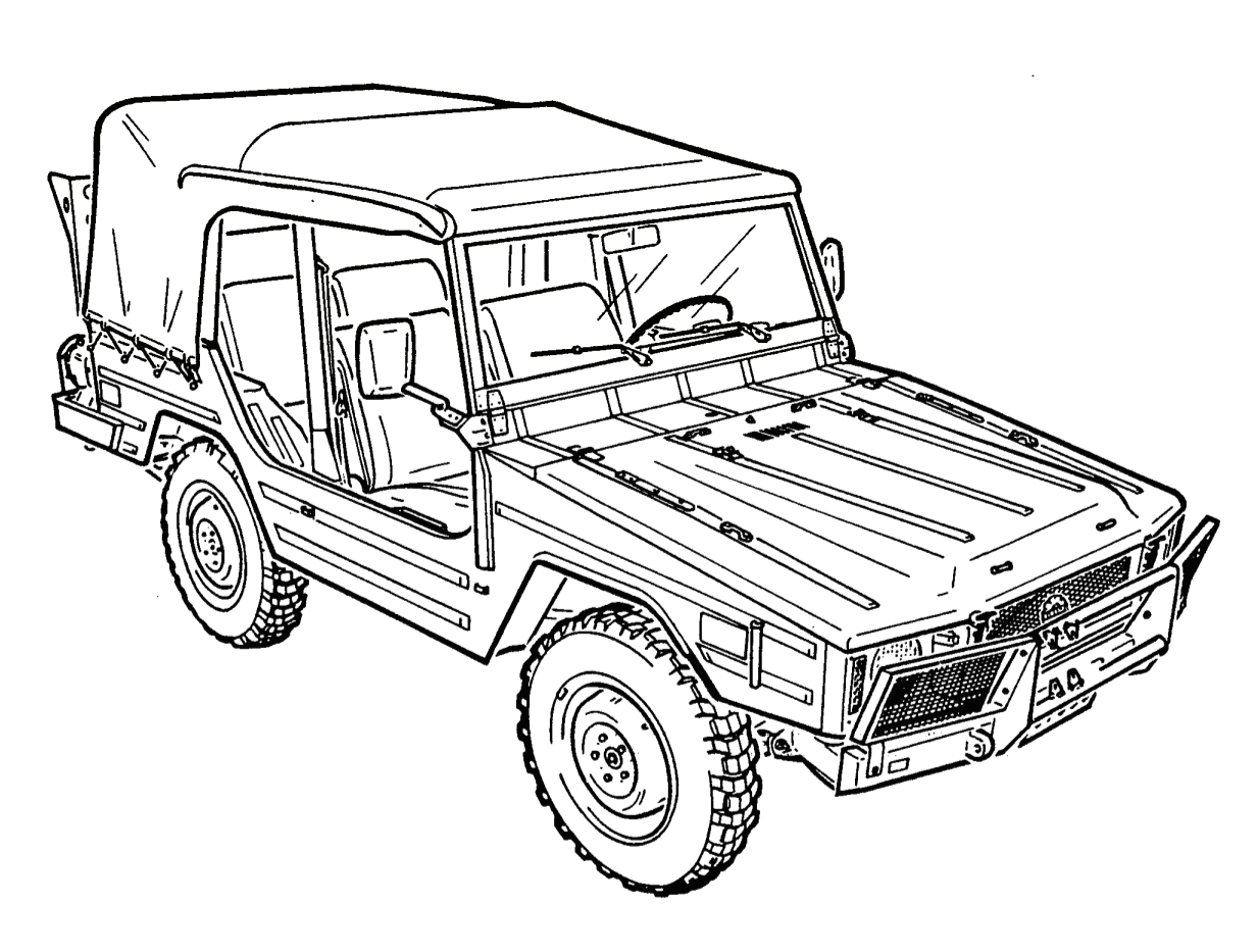
Figure 1-2-1 — Truck, Light, 4 x 4, Military Design, Iltis Canadian, BasicClick image to enlarge.
Vehicle Data
7. Figure 1-2-2, Figure 1-2-3, Figure 1-2-4 and Figure 1-2-5 contain, in tabular form, data applicable to the basic truck series.
| Weights (kg) without crew Maximum capacity |
||||
|---|---|---|---|---|
| Vehicle configuration | Description | Curb weight | Cross-country | Highway |
| Basic | Payload | *365 kg | 500 kg | |
| Front Axle | 705 kg | - | 1,000 kg | |
| Rear Axle | 730 kg | - | 1,250 kg | |
| Total Weight | 1,435 kg | 1,800 kg | 2,050 kg | |
| Maximum Towed Load | 482 kg | 595 kg | ||
| Shipping Volume (m) | 11 m | 11 m | 11 m | |
* Weight placed over rear axle Figure 1-2-2 — Weights and Loads
| Description | Dimensions |
|---|---|
| Overall Length | 3,974 mm |
| Overall Width | 1,520 mm |
| Height | 1,837 mm |
| Wheelbase | 2,017 mm |
| Angle of Approach | 41 degrees |
| Angle of Departure | 32.50 degrees |
| Ground Clearance (under axles) (under chassis) | 250 mm 338 mm |
| Turning Radius: - Right turn - Left turn | 5.5 m 5.5 m |
Figure 1-2-3 — Dimension Data
| Description | Capacity |
|---|---|
| Cooling system | 7.5 Litres |
| Crankcase (without filter) (with filter) | 4.0 Litres 4.5 Litres |
| Windshield washer | 1.7 Litres |
| Gasoline Tank | 82 Litres |
| Transaxle | 3.6 Litres |
| Rear Differential | 1.6 Litres |
Figure 1-2-4 — Capacities
| Tire Size | 6.50 R 16 (Michelin XC Type L) |
| Tire pressure (cold) | ||||
|---|---|---|---|---|
| Front | Rear | |||
| Operating conditions | kPA | psi | kPa | psi |
| Highway | 250 | 36 | 300 | 44 |
| Cross-country | 250 | 36 | 300 | 44 |
| Mud, Sand, Snow | 250 | 36 | 300 | 44 |
Figure 1-2-5 — Tire Size and Inflation Data