
C-30-108-000/ME-001 - Relocation of Spare Wheel Carrier and Fuel Can Bracket
1986-11-1020 Pages

C-30-108-000/ME-001
Installation Instruction
Relocation of Spare Wheel Carrier and Fuel Can Bracket
Truck, Utility, Light, 4 x 4, Military Design, Iltis, Canadian Series
Issued on Authority of the Chief of the Defence Staff
Contact Officer: DSVEM 2-2
OPI: DSVEM
Copyright © 1986 by DND Canada
1986-11-10

Purpose
1.To relocate the spare wheel carrier and fuel can bracket from the side of the vehicle to the rear of the vehicle.
When Modification Shall Be Embodied
2.When authorized by the LCMM.
Installations Affected
3.
- Spare Wheel Carrier Assembly.
- Fuel Can Bracket Assembly.
Equipment/Materiel Affected
4.All Trucks, Utility, Light, 4 x 4, w/tailgate, authorized by the LCMM.
By Whom Work Shall Be Performed
5.
- First line maintenance organizations.
- Units without resources shall request second line maintenance services.
Resources Required
- Manpower — Veh Tech 411 — 2.5 man-hour.
- Downtime — 3 hours.
- Materiel Required - The following item is required:
Installation Procedures
7.When removing the spare wheel carrier and fuel can bracket, all bolt holes must be plugged using the previously removed bolts, washers and nuts. Before installing the old bolts, spread silicon or rubber sealant around the edge of the holes to prevent rust.
Spare Wheel Carrier Removal
8.To remove the spare wheel carrier, proceed as follows:
- Remove and retain the wheel carrier lower mounting screws, nuts and washers.
- Remove the wheel carrier upper mounting screws and remove the wheel carrier assembly. Retain the nuts and discard the screws.
- Apply silicone or rubber sealant around the circumference of each hole in the vehicle body where the screws have been removed.
- Plug the upper holes in the vehicle body using the previously removed nuts and the M8 x 16 mm long screws, see paragraph 6. Item 16.
- Plug the lower holes using the previously removed screws, nuts and washers.
- Tighten all nuts and wipe off all excessive sealant.
- Retain the spare wheel carrier assembly for installation.
Spare Wheel Carrier Installation
9.Before installing the spare wheel carrier ensure the vehicle tailgate is properly locked in the closed position. To install the spare wheel carrier to the rear of the vehicle as follows:
NOTE — All reference numbers shown in parentheses ( ) refer to the item numbers in paragraph 6.
- See Figure 1. Remove and discard the two existing screws located directly below the vehicle right side tailgate securing latch.
- See Figure 3. Remove and discard the two existing screws located under the vehicle tailgate and immediately to the left of the tailgate right side hinge. If the screws are rusted, use penetrating oil to loosen.
- Install the previously removed spare wheel carrier assembly so the right arm of the carrier fits through the installed clamp (see Figure 1).
- With an 8 mm drill bit, and using the spare wheel carrier as a template, drill through the three existing left side holes in the carrier cross-member and through the tailgate.
NOTE — Do not drill through the fourth hole which is located near the upper mounting clamp, see Figure 1.
Fuel Can Bracket Removal
10. To remove the fuel can bracket, which is located on the left rear side of the vehicle, proceed as follows:
- Remove the screws which secure the strap retainer. Retain the screws, nuts and washers. Discard the strap retainer assembly.
- Remove the screws which secure the fuel can bracket to the vehicle body. Retain the screws, nuts, washers and fuel can bracket with strap. Discard the two wooden spacers.
- Apply silicon or rubber sealant around the circumference of each hole in the vehicle body where screws have been removed.
- Plug all the holes using the previously removed screws, nuts and washers. Tighten nuts and wipe off all excessive sealant.
Fuel Can Bracket Installation
11.To install the fuel can bracket to the rear of the vehicle, proceed as follows:
NOTE — All reference numbers shown in parentheses ( ) refer to the item numbers in paragraph 6.
- See Figure 7. Remove and discard the three existing 6 mm screws located approximately 9 mm to the left of the tailgate.
NOTE — Before drilling the holes, ensure the tailgate is locked in the closed position.
- See Figure 8. Measure and scribe the location of the fuel can strap retainer on the upper left corner of the tailgate, above the latch assembly.
- With an 8 mm drill bit, drill two holes through the tailgate.
- Before tightening, adjust the strap buckle to suit the installation.
References
12.LETE task number 83603-L035.
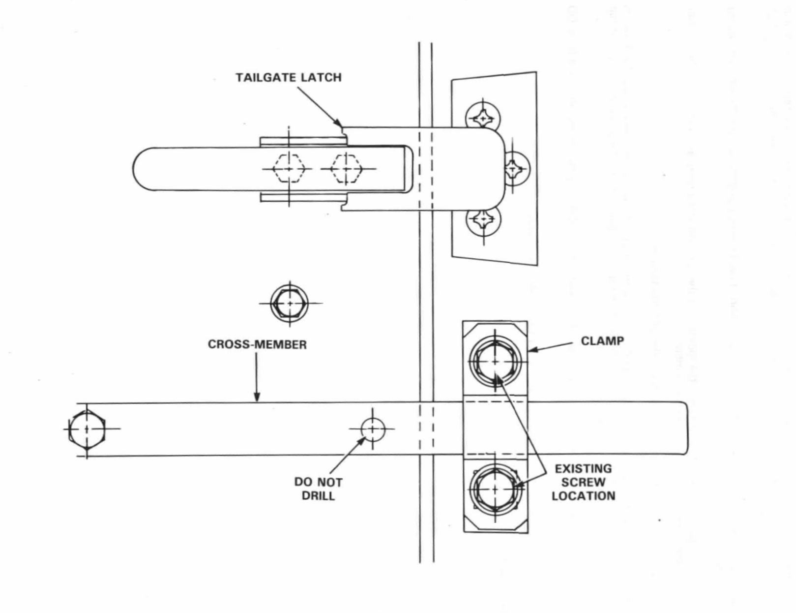
Figure 1 — Location of Spare Wheel Carrier Upper Mounting ClampClick image to enlarge.
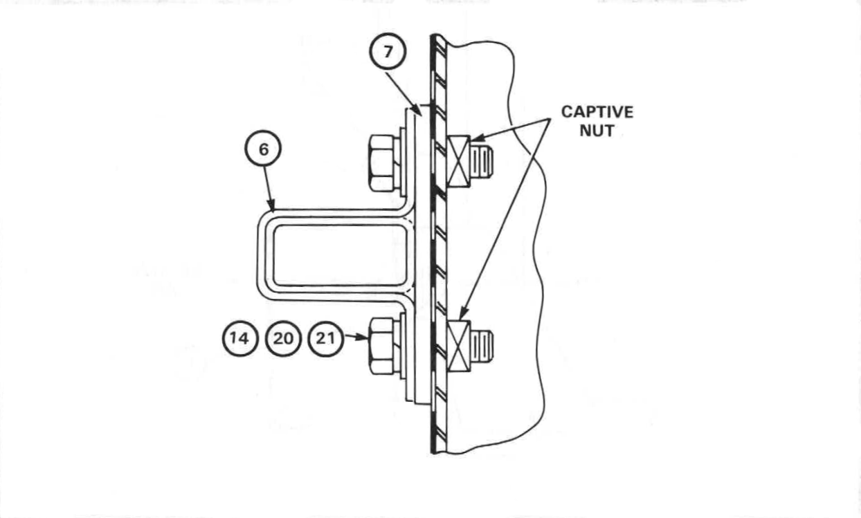
Figure 2 — Installation of Wheel Carrier Upper Mounting ClampClick image to enlarge.
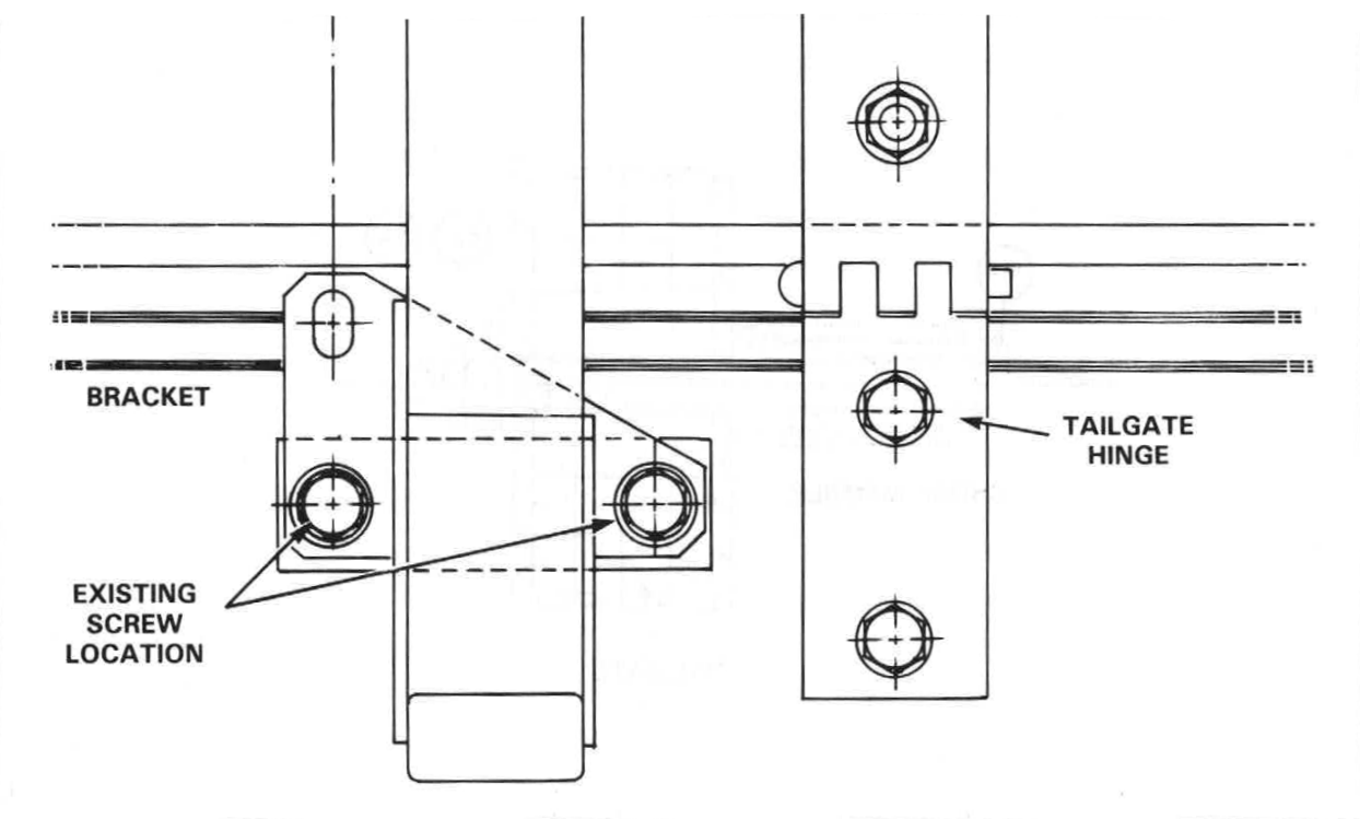
Figure 3 — Location of Spare Wheel Carrier Lower Mounting BracketClick image to enlarge.
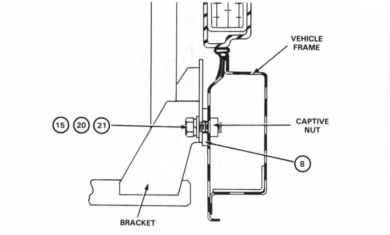
Figure 4 — Securing Wheel Carrier Lower Mounting BracketClick image to enlarge.
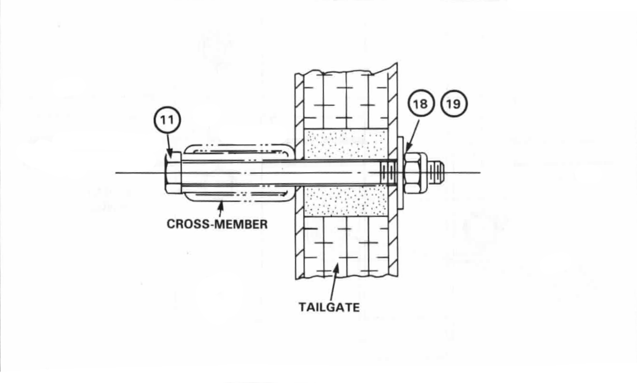
Figure 5 — Securing Carrier Cross-Member to Tailgate
Click image to enlarge.
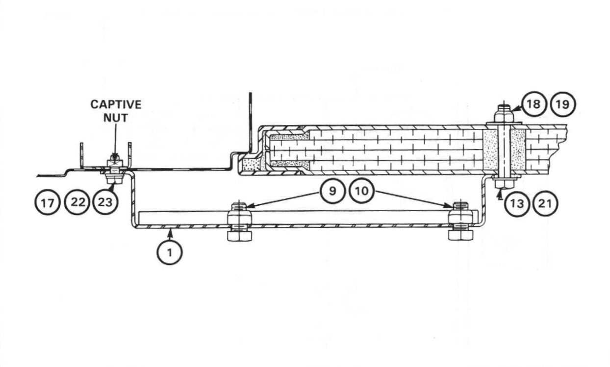
Figure 6 — Installing Fuel Can Bracket SupportClick image to enlarge.
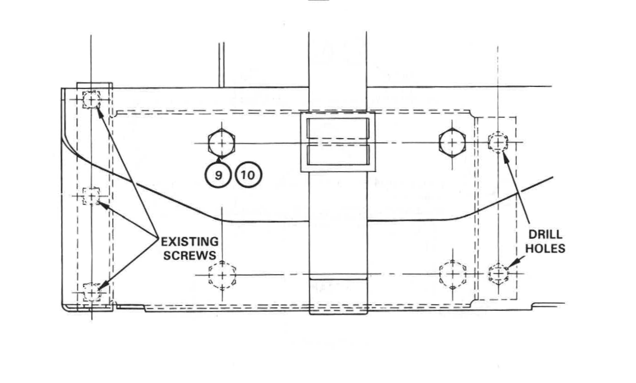
Figure 7 — Installing Fuel Can Bracket
Click image to enlarge.
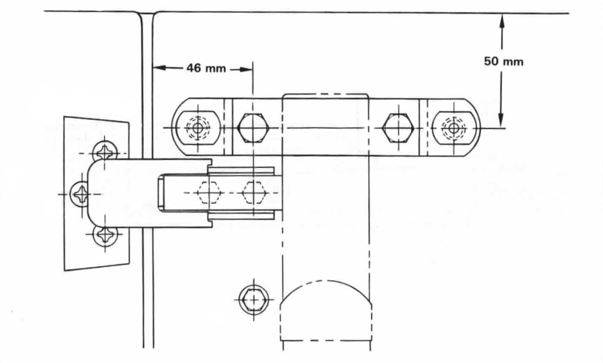
Figure 8 — Measuring Location of Fuel Can Strap RetainerClick image to enlarge.
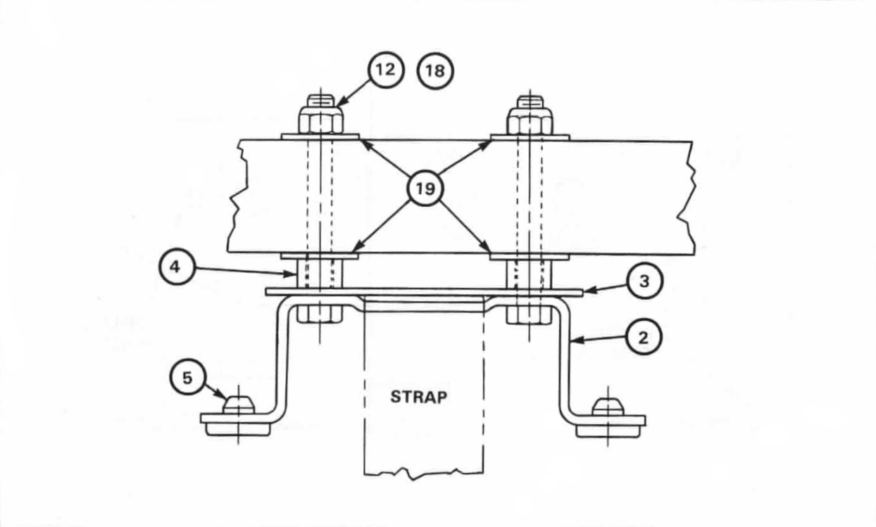
Figure 9 — Installing Fuel Can Strap RetainerClick image to enlarge.